
Cast-in-situ inverted-T-shaped bent cap and pier and pier construction process

A cast-in-place, covering beam technology, applied in bridges, bridge parts, bridge construction, etc., can solve the problems of covering beams, piers and their piers that cannot meet the requirements of safety, civilization, and rapid construction, so as to reduce the interference of ground traffic, The effect of rapid construction reduction and short construction period

Active Publication Date: 2013-12-18
SHANGHAI URBAN CONSTR DESIGN RES INST GRP CO LTD
View PDF8 Cites 8 Cited by
  • Summary
  • Abstract
  • Description
  • Claims
  • Application Information

AI Technical Summary

Problems solved by technology

[0003] With the development of society, the traditional methods of capping girders and bridge piers and their construction techniques gradually cannot meet people's requirements for safety, civilization, rapid construction, and reducing construction interference to ground road traffic.

Method used


Image

  • Cast-in-situ inverted-T-shaped bent cap and pier and pier construction process
  • Cast-in-situ inverted-T-shaped bent cap and pier and pier construction process
  • Cast-in-situ inverted-T-shaped bent cap and pier and pier construction process

Examples


Embodiment 1

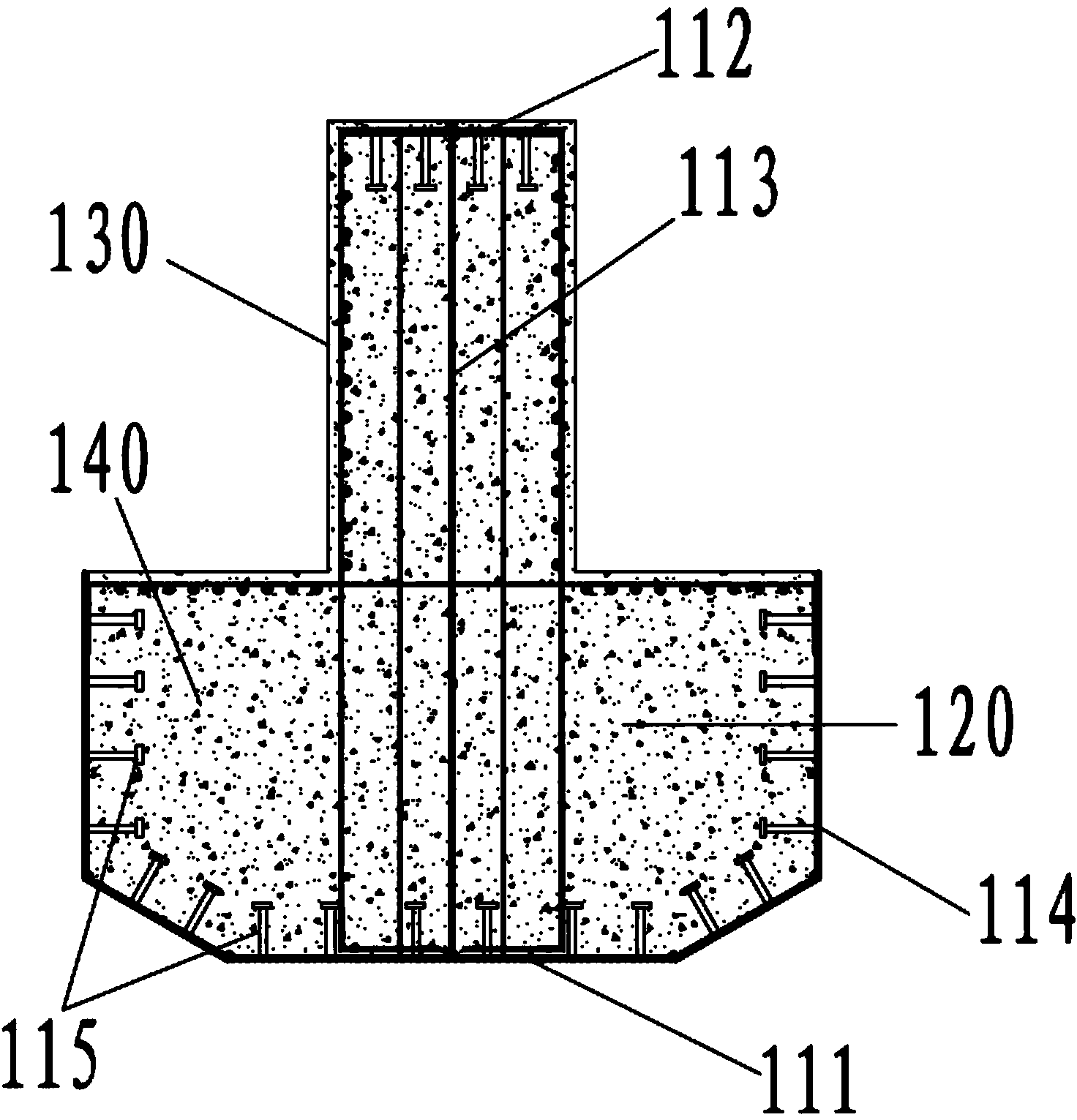
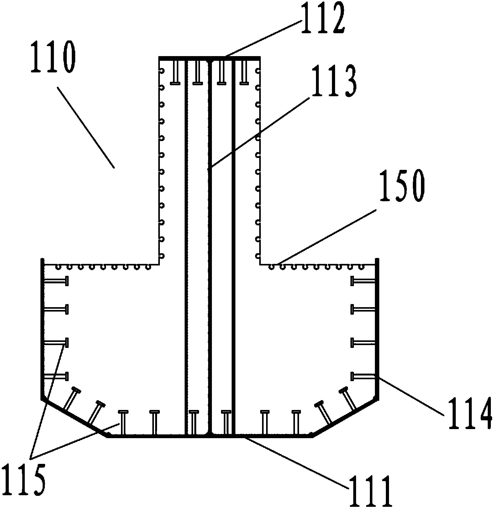
[0030] figure 1 It is the structural representation of the cast-in-place inverted T-shaped cap beam of Embodiment 1, figure 2 for figure 1 Sectional view of A-A section. Such as figure 1 with figure 2 As shown, this specific embodiment proposes a cast-in-place inverted T-shaped cover beam 100, which includes a rigid framework 110 and a concrete structure 120 poured in the rigid framework 110. which, combined with image 3 As shown, the rigid frame 110 includes a lower baffle 111, an upper baffle 112, a connecting plate 113 and a side baffle 114, the lower baffle 111, the upper baffle 112 and the connecting plate 113 are connected to form an I-shaped steel structure, and the side baffle 114 It is two pieces, respectively arranged on the two sides of the lower baffle 111 and extending upwards. The lengths of the lower baffle 111, the upper baffle 112, the connecting plate 113 and the side baffle 114 are all the same as the length of the inverted T-shaped cover beam 100. ...

Embodiment 2

[0034] Figure 4 It is the structural representation of the bridge pier of embodiment two, Figure 5 for Figure 4 The B-B cross-sectional view, Image 6 for Figure 5 C-C section cutaway view. Such as Figure 4 to Figure 6 As shown, this embodiment proposes a bridge pier, including a column 200 and an inverted T-shaped cover beam 100 , and the inverted T-shaped cover beam 100 is arranged on the column 200 . Wherein, the inverted T-shaped cover beam 100 is the cast-in-place inverted T-shaped cover beam described in Embodiment 1, and a perforated steel panel 210 is arranged on the top surface of the column 200, and the perforated steel panel 210 is fixedly connected with the lower baffle plate 111 An anchoring steel bar 220 extends upward from the top of the column 200 , and the anchoring steel bar 220 passes through the perforated steel panel 210 and the reserved hole is anchored to the concrete structure 120 in the rigid framework 110 .

Embodiment 3

[0036] This embodiment proposes a bridge pier construction process, as shown in the accompanying drawings, including the following steps:

[0037] Step S101, prefabricate the rigid skeleton 110 of the first embodiment at the prefabrication site, and construct the column 200 of the second embodiment at the construction site.

[0038] Step S102, transport the rigid frame 110 to the construction site.

[0039] Step S103 , hoisting the rigid framework 110 on the column 200 at the construction site by using hoisting equipment, and inserting the anchor bars 220 on the column 200 into the rigid framework 110 .

[0040] Step S104, the perforated steel panel 210 on the top surface of the column 200 is fixedly connected to the lower baffle plate 111 of the rigid framework 110, such as by surrounding welding, and the rigid framework 110 is temporarily fixed on the column.

[0041] Step S105, using the rigid frame 110 as a concrete pouring formwork to pour the concrete structure 120 to f...


PUM


Abstract

The invention discloses a cast-in-situ inverted-T-shaped bent cap and a pier as well as a pier construction process. The cast-in-situ inverted-T-shaped bent cap comprises a rigid skeleton and a concrete structure, wherein the concrete structure is cast in the rigid skeleton; the rigid skeleton comprises a lower baffle plate, an upper baffle plate, a connecting plate and two side baffle plates, and the lower baffle plate, the upper baffle plate and the connecting plate are connected to form an I-shaped steel structure; the side baffle plates are respectively arranged at the two side edges of the lower baffle plate and extend upwards. The pier comprises a stand column and the cast-in-situ inverted-T-shaped bent cap, wherein the cast-in-situ inverted-T-shaped bent cap is arranged on the stand column. The pier construction process comprises the following steps: because the rigid skeleton is prefabricated, and the stand column is built, the rigid skeleton is lifted on the stand column, and the anchoring steel bar on the stand column is inserted into the rigid skeleton; the rigid skeleton is used as a concrete casting template to cast the concrete structure, and finally the pier is formed. The cast-in-situ inverted-T-shaped bent cap and the pier as well as the pier construction process have the advantages that the construction is convenient, no support or a few supports can be arranged, and the interference on ground traffic is smaller.

Description

technical field [0001] The invention relates to the technical field of bridge construction, in particular to a cast-in-place inverted T-shaped cover beam, a bridge pier and a construction process for the bridge pier. Background technique [0002] In China, the bridge cover beam usually adopts structural types such as a reinforced concrete cover beam or a prestressed concrete cover beam that is formed on a support or bracket, and steel bars are bound on site, and cast-in-situ concrete. [0003] With the development of society, the traditional methods of capping girders and bridge piers and their construction techniques gradually cannot meet people's requirements for safety, civilization, rapid construction, and reduction of construction interference to ground road traffic. [0004] Therefore, those skilled in the art are devoting themselves to the development of a cast-in-place inverted T-shaped cap girder and pier and pier construction technology that is convenient for const...

Claims


Application Information

Patent Timeline
Patent Type & Authority Applications(China)
IPC IPC(8): E01D19/02E01D21/00
Inventor 沙丽新黄锦源吴刚汪瑞俞露唐祖宁丁佳元管闻达周成蒋小路
Owner SHANGHAI URBAN CONSTR DESIGN RES INST GRP CO LTD
Learn More