Eureka AIR delivers breakthrough ideas for toughest innovation challenges, trusted by R&D personnel around the world.

Scanning region positioning device in residual ice detection process of airplane

A technology for detection devices and scanning areas, which is applied in the directions of measuring devices, optical testing of flaws/defects, and material analysis through optical means, which can solve problems such as low scanning efficiency, inability to determine the exact position of residual ice, missed detection, etc., and achieve positioning High precision, fast measurement speed and high efficiency

Inactive Publication Date: 2013-12-18
CIVIL AVIATION UNIV OF CHINA
View PDF4 Cites 6 Cited by
  • Summary
  • Abstract
  • Description
  • Claims
  • Application Information

AI Technical Summary

Problems solved by technology

However, due to the limitation of the size of the detection area, this method cannot complete the detection of residual ice on the surface of the aircraft body at one time, so manual control is required to complete the switching of multiple scanning areas, resulting in low scanning efficiency and easy to cause missed detection
At the same time, this method can only determine the relative position of the residual ice in the imaging area, but cannot determine the exact position of the residual ice in the aircraft coordinate system, which brings difficulties to further residual ice deicing operations

Method used


Image

  • Scanning region positioning device in residual ice detection process of airplane
  • Scanning region positioning device in residual ice detection process of airplane

Examples


Embodiment Construction

[0017] The device for positioning the scanning area in the process of aircraft residual ice detection provided by the present invention will be described in detail below in conjunction with the accompanying drawings and specific embodiments.

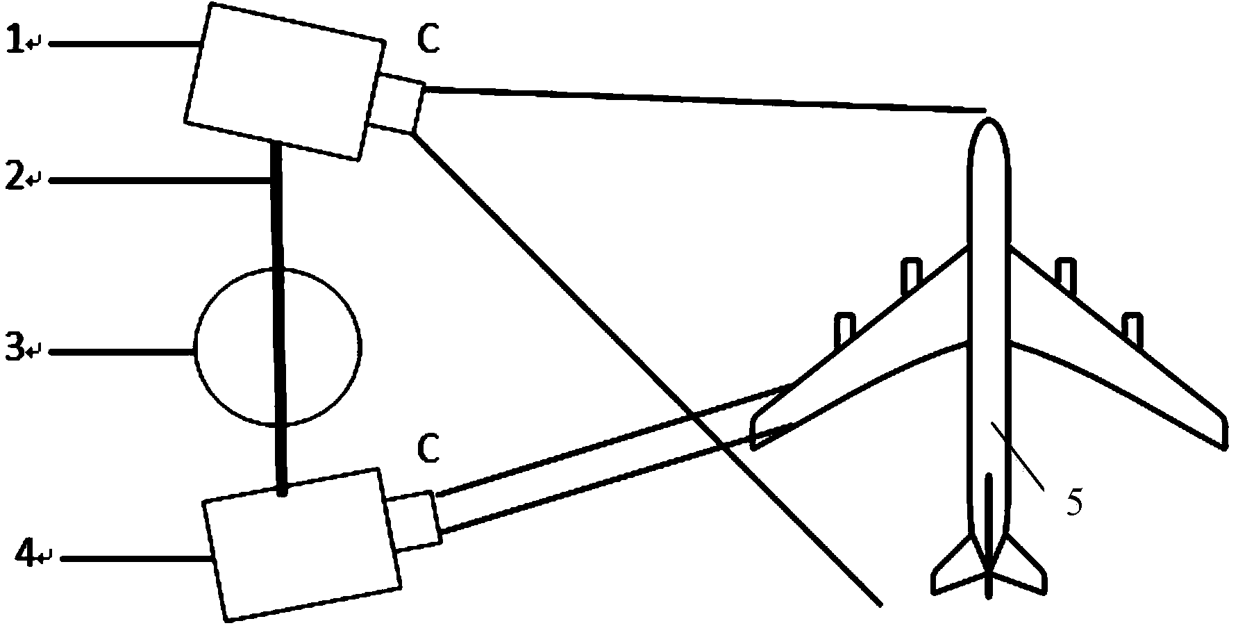
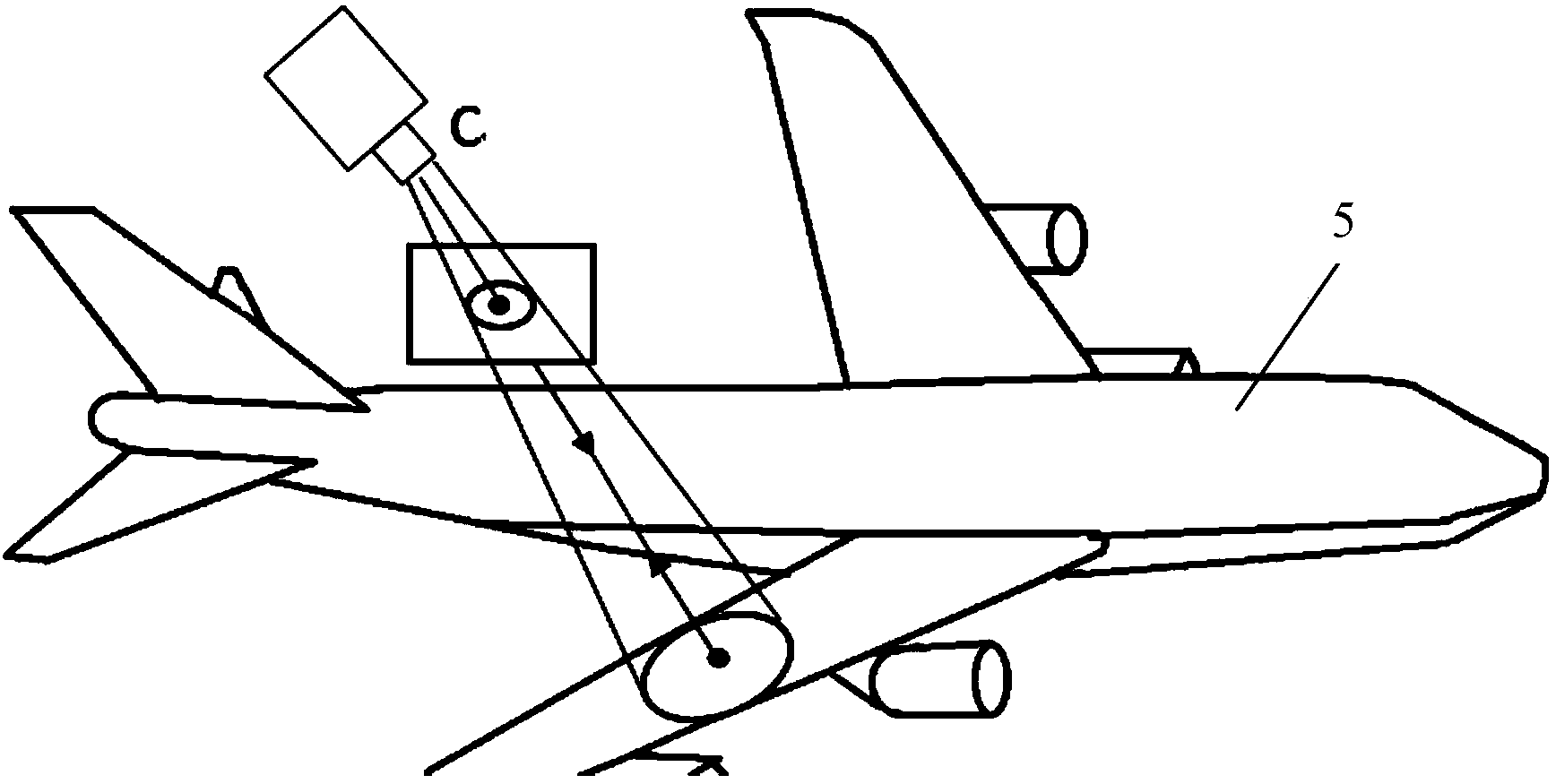
[0018] like figure 1 , figure 2 As shown, the scanning area positioning device in the aircraft residual ice detection process provided by the present invention includes a large field of view visual positioning sensor 1, a fixed bracket 2, a three-degree-of-freedom rotating platform 3, an infrared multi-spectral residual ice detection device 4 and a main control device ;in:

[0019] The lower end of the three-degree-of-freedom rotating platform 3 is fixed on the mobile operating platform of the airport. On the basis of ensuring the relative position and posture relationship between the large-field-of-view visual positioning sensor 1 and the infrared multi-spectral residual ice detection device 4, it realizes omni-directional scanning in...


PUM


Abstract

The invention provides a scanning region positioning device in a residual ice detection process of an airplane. The scanning region positioning device comprises a large-view-field visual positioning sensor, a fixed bracket, a three-degree-of-freedom rotary platform, an infrared multispectral residual ice detection device and a main control device, wherein the fixed bracket is mounted at the upper end of the three-degree-of-freedom rotary platform; the two ends of the fixed bracket are connected with the large-view-field visual positioning sensor and the infrared multispectral residual ice detection device respectively; the main control device is connected with the large-view-field visual positioning sensor, the infrared multispectral residual ice detection device and the three-degree-of-freedom rotary platform. According to the scanning region positioning device, based on inherent geometrical characteristics of the detected airplane, a method for combining the large-view-field visual positioning sensor and the infrared multispectral residual ice detection device is adopted; coordinates of a scanning region and a residual ice position under an airplane body coordinate system can be determined through the device relative to a posture estimation algorithm and a coordinate conversion method of an airplane body, so that automatic positioning of the scanning region and the residual ice position can be realized; a scanning process is controlled automatically; the scanning region positioning device has the characteristics of high measurement speed, high efficiency, high positioning precision and the like.

Description

technical field [0001] The invention belongs to the technical field of automatic detection devices, and in particular relates to a scanning area positioning device in the detection process of aircraft residual ice. Background technique [0002] Once the surface of the aircraft is polluted by pollutants such as ice, snow, frost, etc., it will directly affect the aerodynamic characteristics and flight safety of the aircraft. For example, an increase in the thickness of the wing surface will directly affect the airflow in the boundary layer, thereby changing the aerodynamic characteristics of the local wing. Studies have shown that the maximum lift of the wing will be significantly reduced for every increase of 0.3mm frost layer thickness on the 3m chord wing. Similarly, when the icing on the leading edge of the wing is distributed in a gradient and the crosswind takes off at a high angle of attack, small ice, snow and frost pollutants may cause catastrophic consequences such ...

Claims


Application Information

Patent Timeline
IPC IPC(8): G01N21/01G01N21/88
Inventor 诸葛晶昌于之靖高建树郑大川
Owner CIVIL AVIATION UNIV OF CHINA
Why Eureka
Eureka Blog
Learn More