Automatic assembly device and assembly method of valve stem sealing ring

An automatic assembly device and automatic assembly technology, applied in the direction of metal processing, metal processing equipment, manufacturing tools, etc., can solve problems such as difficulty in adapting to the needs of automatic assembly market competition, unstable quality, inconvenient installation work, etc., to improve product qualification rate and assembly efficiency, reducing production costs and reducing labor intensity

Inactive Publication Date: 2016-01-13
TAIZHOU LIANFANG ELECTROMECHANICAL TECH
View PDF7 Cites 0 Cited by
  • Summary
  • Abstract
  • Description
  • Claims
  • Application Information

AI Technical Summary

Problems solved by technology

As the shape of the workpiece is getting smaller and smaller, the size of the O-ring is getting smaller and smaller, which brings great inconvenience to the installation work.
[0004] The assembly of the existing O-rings generally relies on manual assembly, resulting in a high failure rate of the product, and the assembly efficiency is limited, which is time-consuming and laborious, and greatly increases the production cost.
At the same time, due to the low assembly speed of manual operation, it is difficult to adapt to the needs of automated assembly and the fierce market competition.
[0005] Especially the valve stem, which is the core part of the faucet valve core and ball valve, has high sealing requirements and large output, and often requires a lot of labor to assemble the sealing ring, which is not only time-consuming and laborious, but also high cost, low efficiency, and poor quality. Stablize

Method used


Image

  • Automatic assembly device and assembly method of valve stem sealing ring
  • Automatic assembly device and assembly method of valve stem sealing ring
  • Automatic assembly device and assembly method of valve stem sealing ring

Examples


Embodiment Construction

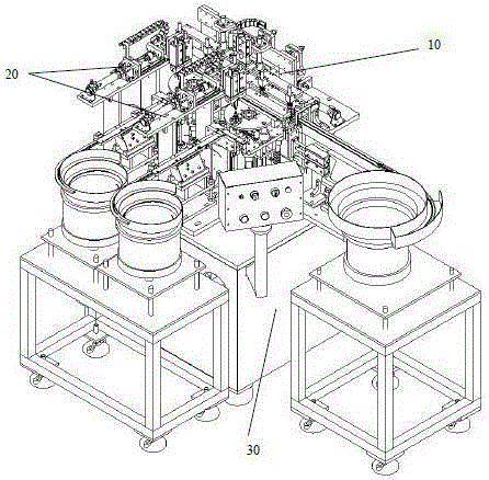
[0092] like figure 1 As shown, the automatic assembly device of the valve stem sealing ring of the present invention includes a valve stem automatic feeding device 10, two sets of sealing ring automatic assembly devices 20, a bed frame 30, the valve stem automatic feeding device 10 and the sealing ring automatic assembly The device 20 is arranged on the bed frame 30; the inside of the bed frame 30 is provided with an electromechanical control system and a pneumatic control system of the machine tool;

[0093] The valve stem automatic feeding device 10 separates the valve stems from the feeding system one by one, and moves the valve stems one by one to the position to be assembled in an orderly manner, so as to realize the automatic feeding of the valve stems; Automatic assembly of the stem sealing ring; finally, the valve stem after assembly is transferred and discharged;

[0094] Two sets of sealing ring automatic assembly devices 20 respectively complete the automatic feedi...


PUM


Abstract

The invention discloses an automatic assembling device for valve rod sealing rings. The automatic assembling device comprises an automatic valve rod feeding device and two sets of automatic sealing ring assembling devices, wherein the automatic valve rod feeding device sequentially moves valve rods to positions to be assembled for realizing the automatic feeding of the valve rods; after the automatic valve rod feeding device positions the valve rods and tightly presses the valve rods, the automatic feeding and ring supporting actions of O-shaped sealing rings are respectively completed by the two sets of automatic sealing ring assembling devices, in addition, the supported O-shaped sealing rings are pushed into grooves of the valve rods in the two positions to be assembled of the valve rods, and the automatic assembly of the two sealing rings is completed; finally, the assembled valve rods are conveyed and discharged. The automatic assembling device has the advantages that the assembly automation of the valve rod sealing rings can be realized, the defects of low assembly speed and automation assembly adaption difficulty of manual operation can be overcome, the product qualification rate and the assembly efficiency are greatly improved, and in addition, the work intensity, the labor and the production cost are reduced. The invention also discloses an automatic assembling method for the valve rod sealing rings.

Description

technical field [0001] The invention relates to an automatic assembly device, in particular to an automatic assembly device for a sealing ring of a valve stem. The invention also relates to an automatic assembly method for the sealing ring of the valve stem. Background technique [0002] O-rings are the most commonly used seal rings. O-ring is the most widely used seal on various mechanical equipment. Its cross-sectional structure is extremely simple, and it has a self-sealing function and reliable sealing performance. It is mainly used for static sealing and reciprocating motion sealing. [0003] In order to improve the sealing effect on the workpiece, it is necessary to insert the O-shaped sealing ring into the groove of the workpiece. When installing, the O-shaped sealing ring should be stretched and passed over any end of the workpiece before being inserted into the groove. As the shape of the workpiece is getting smaller and smaller, the size of the O-ring is also get...

Claims


Application Information

Patent Timeline
Patent Type & Authority Patents(China)
IPC IPC(8): B23P19/04B23P19/00
Inventor 武建伟许方富舒勤业陈思涵陈伟强
Owner TAIZHOU LIANFANG ELECTROMECHANICAL TECH
Why Eureka
Try Eureka