
Roving frame transmission device

A technology of transmission device and roving frame, which is applied in the direction of spinning machine, continuous winding spinning machine, textile and paper making, etc. It can solve the problem of poor balance and stability of dragon tendon lifting, poor torsional rigidity of lifting drive shaft, and influence on winding The quality of the formed rovings and other issues can be solved to ensure balance and stability, good torsional rigidity, and improve the quality of the rovings

Active Publication Date: 2013-12-25
WUXI HONGYUAN ELECTROMECHANICAL TECH
View PDF6 Cites 4 Cited by
  • Summary
  • Abstract
  • Description
  • Claims
  • Application Information

AI Technical Summary

Problems solved by technology

After the design of the extended roving frame, if the original lower rib lifting transmission device is installed at one end of the main machine, there will be the following disadvantages: 1) The torsional rigidity of the lifting transmission shaft is poor; 2) The torque on the lifting transmission shaft is large; 3. ) The balance and stability of the dragon tendon lifting are poor; 4) It affects the winding forming and roving quality

Method used


Image

  • Roving frame transmission device
  • Roving frame transmission device
  • Roving frame transmission device

Examples


Embodiment 1

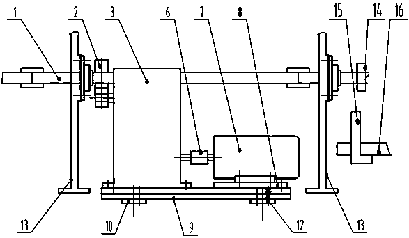
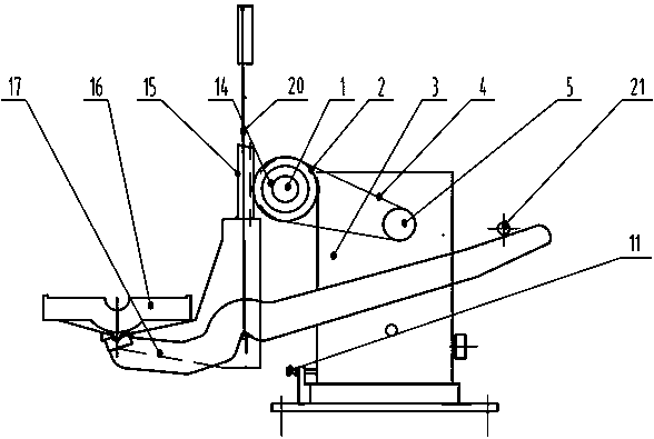
[0016] Example 1: A roving frame transmission device, comprising a lifting transmission shaft 1, a driven pulley 2, a reducer 3, a transmission belt 4, a driving pulley 5, an elastic coupling 6, a lifting motor 7, a small bottom plate 8, a large bottom plate 9, and a connecting bottom plate 10. Adjusting screw 11, fixing screw 12, wall plate 13, gear 14, dragon tendon support rack 15, dragon tendon 16, dragon tendon lever 17, weight sliding wheel 18, weight 19 and chain 20, lifting transmission shaft 1 Transversely through the front and rear frames of the roving frame, such as figure 2 As shown, the reducer 3 and the lifting motor 7 are arranged in the middle between two adjacent wallboards 13, the lifting motor 7 is installed on the small bottom plate 8, and the left side of the large bottom plate 9 is installed with a reducer composed of bevel gears and worm gears. 3. The small base plate 8 on which the lifting motor 7 is installed is slidably fixed on the large base plat...


PUM


Abstract

The invention discloses a roving frame transmission device. A lifting transmission shaft horizontally penetrates through a headstock and a tailstock machine frame of a roving frame and is driven to perform forward and reverse rotation by a transmission shaft driving device installed between two adjacent wallboards, a gear is installed on the lifting transmission shaft extending out of one side of a wall, a keel is installed at the bottom end of a keel supporting foot rack meshed with the gear, the bottom of the keel is connected with one end of a keel lever, the other end of the keel lever is provided with a supporting point, and a balance mechanism enabling the keel lever to be balanced is lifted on the keel lever. The roving frame transmission device can provide invariable balance force large in weight to act on the lever, stable balancing moment is generated, on one hand, torque borne by the lifting transmission shaft in the keel lifting process can be shared, on the other hand, balance and stability in the lifting process can be guaranteed, keel shaking caused by increase of spindles on the keel is avoided, the roving frame keel lifting transmission shaft is good in torsional rigidity, the torque borne by the lifting transmission shaft is small, and rough yarn is formed and packaged well.

Description

technical field [0001] The invention relates to the field of cotton textile machinery and equipment, in particular to a transmission device for a roving frame. Background technique [0002] In the cotton spinning spindle roving frame, the lifting transmission of the lower dragon bar is not only responsible for the transmission of the bobbin, but also ensures that the winding angular velocity decreases with the increase of the bobbin diameter, so that it can generate the winding speed and meet the winding forming conditions. Mainly in order to ensure the up and down movement of the lower rib, the change of the lifting stroke is completed through the control of the motor and PLC: 1) The lifting stroke decreases with the increase of the diameter of the bobbin, shortening the lifting stroke of the dragon tendon, that is, the roving is After each layer is wound on the bobbin, the forming angle period is shortened by Δt, so that the upper and lower forming angles of the roving pac...

Claims


Application Information

Patent Timeline
Patent Type & Authority Applications(China)
IPC IPC(8): D01H1/20
Inventor 缪小方张始荣丁坚庄玮付光怀
Owner WUXI HONGYUAN ELECTROMECHANICAL TECH
Learn More