

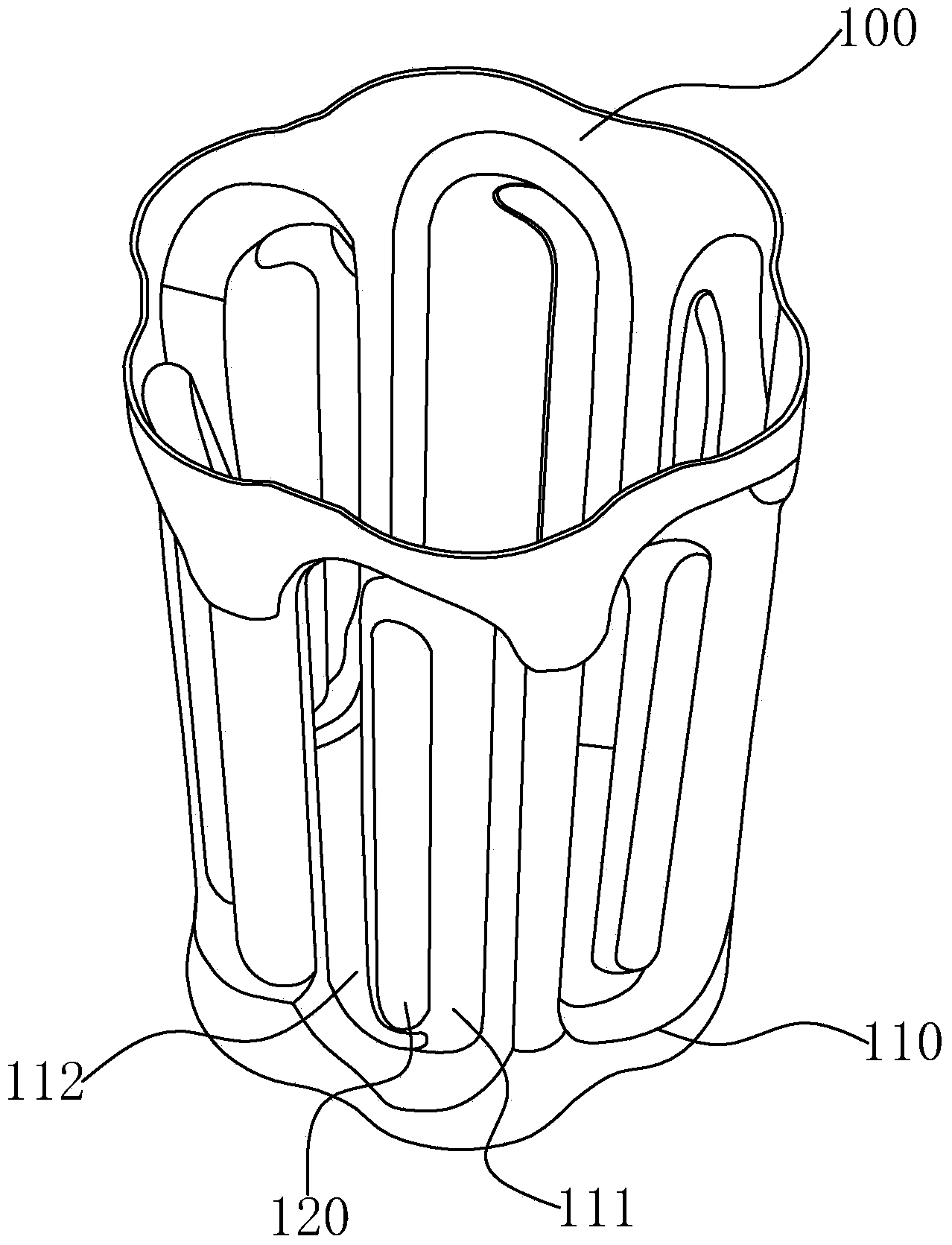
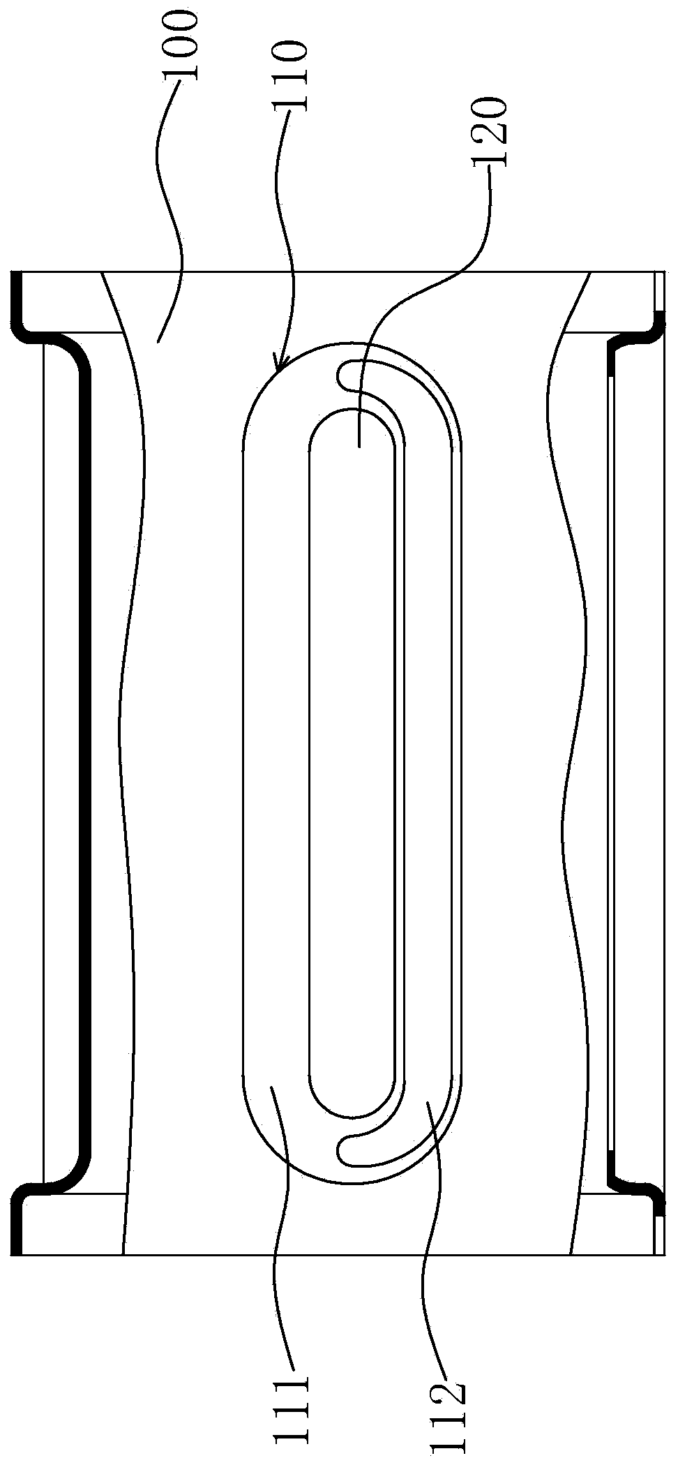
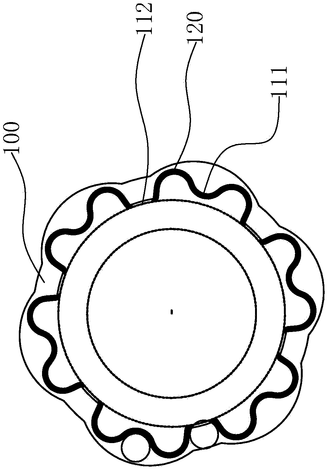
Linear bearing retainer
A linear bearing and cage technology, applied in the field of bearings, can solve the problems of increasing friction between the bearing and the fixed shaft, reducing the bearing stability, increasing the load of the linear bearing, etc., so as to reduce the friction, make full use of the plate, and improve the overall accuracy. Effect
- Summary
- Abstract
- Description
- Claims
- Application Information
AI Technical Summary
Problems solved by technology
Method used
Image

Examples
Embodiment 1
[0054] S1. According to the components and mass percentages of the linear bearing cage in Example 1 in Table 1, the raw materials were prepared, and the raw materials were crushed and refined into metal powder by ball milling, and pre-annealed at 680°C under hydrogen or vacuum conditions Processing, removing impurities, classifying the powder according to the particle size, blending the metal powders of different components at different levels by mechanical means, and making the powder of small particles into large particles or aggregates after blending;
[0055] S2, rolling the large particle or aggregate powder prepared in step S1 into a plate-shaped blank under a pressure of 400 MPa, and sintering at 1000° C. for 3 hours to obtain a semi-finished plate;
[0056] S3. Heat-treat the semi-finished plate, normalize at 1020°C for 4 hours, take out the furnace and air cool; quench at 860°C for 3 hours, water cool to room temperature; temper at 200°C for 2 hours, and air cool to ob...
Embodiment 2
[0065] S1. According to the components and mass percentages of the linear bearing cage in Example 2 in Table 1, the raw materials were prepared, and the raw materials were crushed and refined into metal powder by ball milling, and pre-annealed at 700°C under hydrogen or vacuum conditions Processing, removing impurities, classifying the powder according to the particle size, blending the metal powders of different components at different levels by mechanical means, and making the powder of small particles into large particles or aggregates after blending;
[0066] S2. Roll the large particle or aggregate powder prepared in step S1 into a plate-shaped blank under a pressure of 350 MPa, and sinter at 980° C. for 2 hours to obtain a semi-finished plate;
[0067] S3. Heat-treat the semi-finished plate, normalize it at 1060°C for 4 hours, take it out of the furnace and air-cool it; quench it at 850°C for 2 hours, then water-cool it to room temperature; temper it at 180°C for 2 hours,...
Embodiment 3
[0071]S1. According to the components and mass percentages of the linear bearing cage in Example 3 in Table 1, the raw materials were prepared, and the raw materials were crushed and refined into metal powder by ball milling, and pre-annealed at 710°C under hydrogen or vacuum conditions Processing, removing impurities, classifying the powder according to the particle size, blending the metal powders of different components at different levels by mechanical means, and making the powder of small particles into large particles or aggregates after blending;
[0072] S2. Roll the large particle or aggregate powder prepared in step S1 into a plate-shaped blank under a pressure of 500 MPa, and sinter at 1050° C. for 4 hours to obtain a semi-finished plate;
[0073] S3. Heat-treat the semi-finished plate, normalize at 1080°C for 5 hours, take out the furnace and air-cool; quench at 830°C for 3 hours, and water-cool to room temperature; temper at 210°C for 4 hours, and air-cool to obtai...
PUM
 Abstract
Description
Claims
Application Information