
Automatic energy dispersive X-ray fluorescence analysis test platform

A fluorescence analysis and testing platform technology, which is applied in the analysis of materials, material analysis using wave/particle radiation, and measuring devices, etc., can solve the problem that the distance between the sample and the detector cannot be accurately controlled, and the distance of movement cannot be accurately controlled. Uneven characteristic X-ray divergence and other problems, to achieve the effect of strong measurement reliability, enhanced detection ability, and extremely high failure rate

Active Publication Date: 2013-12-25
四川新先达测控技术有限公司
View PDF16 Cites 10 Cited by
  • Summary
  • Abstract
  • Description
  • Claims
  • Application Information

AI Technical Summary

Problems solved by technology

[0007] 1. In the way of fixing the sample directly above the detector, the detector will often be polluted because the sample dust falls on the detector;
[0008] 2. In the way of pushing samples in parallel, the sample table is often polluted due to the collapse of the sample, which is not easy to clean;
[0009] 3. In the three-dimensional push method, although the sample can reach the designated position by setting the moving distance in the X, Y, and Z directions, the precise control of the moving distance is often not achieved, which makes the distance between the sample and the detector Distance cannot be precisely controlled
In this way, the degree of wear and tear of the instrument
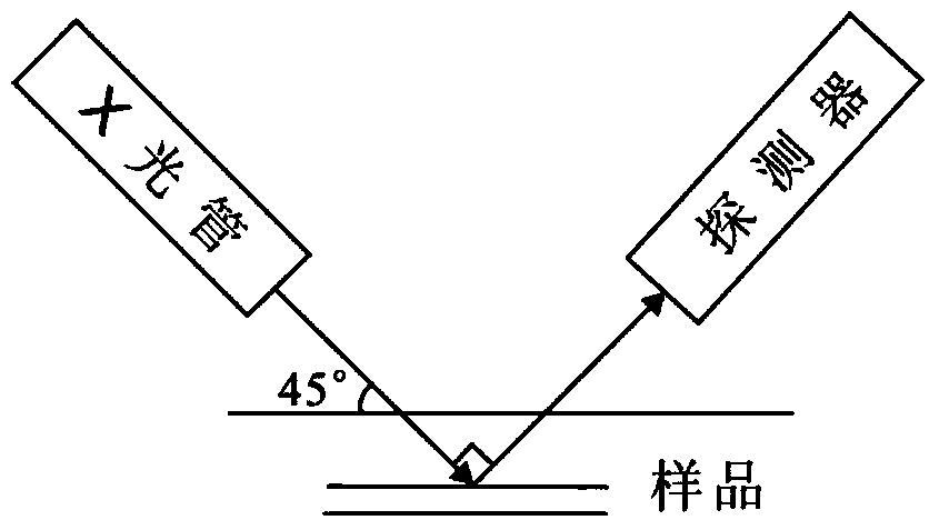
[0010] Second, during the detection process, X-rays are incident from an angle. Since the sample is in a static state, the characteristic X-rays often diverge unevenly, resulting in low detection efficiency.
[0011] Third, for elements with a small atomic number, the characteristic X-ray energy is small, which is easily absorbed by the air, making the detection efficiency of these light elements in the measurement process not high

Method used


Image

  • Automatic energy dispersive X-ray fluorescence analysis test platform
  • Automatic energy dispersive X-ray fluorescence analysis test platform
  • Automatic energy dispersive X-ray fluorescence analysis test platform

Examples


Embodiment Construction

[0035] In order to make the purpose, technical solution and advantages of the present application clearer, the present application will be further described in detail below in conjunction with the accompanying drawings and specific embodiments.

[0036] In the following description, references to "one embodiment," "an embodiment," "an example," "example," etc. indicate that such described embodiment or example may include a particular feature, structure, characteristic, property, element, or limitations, but not every embodiment or example necessarily includes the specific feature, structure, characteristic, property, element or limitation. Additionally, repeated use of the phrase "according to one embodiment of the present application" does not necessarily refer to the same embodiment, although it may.

[0037] For simplicity, some technical features known to those skilled in the art are omitted from the following description.

[0038] The invention provides an automatic ene...


PUM

PropertyMeasurementUnit
angleaaaaaaaaaa

Abstract

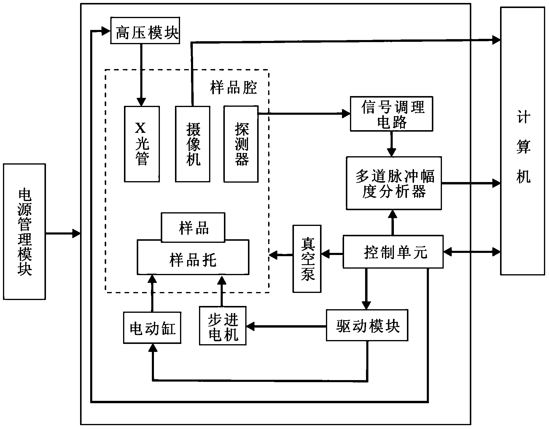
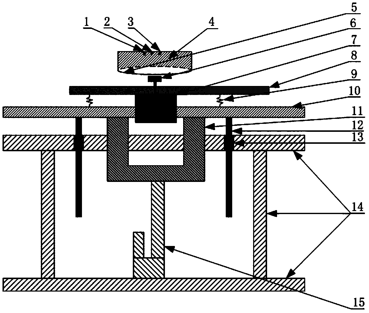
The invention discloses an automatic energy dispersive X-ray fluorescence analysis test platform. The automatic energy dispersive X-ray fluorescence analysis test platform comprises a sample chamber, a stepping motor and an electric cylinder. The sample chamber and a seal plate form a closed chamber. The stepping motor is fixed to a tray. The tray is connected to a bracket. The bracket is connected to the electric cylinder. A rotation shaft of the stepping motor passes through the seal plate and enters into the closed chamber. The rotation shaft of the stepping motor is provided with a sample support. The sample chamber is provided with an X-ray pipe, a camera and a detector. The closed chamber is communicated with a vacuum pump. The camera is connected to a computer. The automatic energy dispersive X-ray fluorescence analysis test platform reduces measure errors, reduces detector-caused pollution, improves a light element detection capability and improves detection efficiency.

Description

technical field [0001] The invention belongs to the field of analysis and test equipment, and relates to a fluorescence spectrometer, in particular to an automatic energy dispersion X fluorescence analysis and test platform. Background technique [0002] The energy dispersive X-ray fluorescence spectrometer is configured according to the X-ray fluorescence spectroscopic analysis method. It can analyze the composition content of various elements in solid or powder samples. It has the characteristics of high sensitivity, good precision, stable performance, and fast analysis speed. It is a A small and medium-sized, economical, high-performance energy dispersive X-ray spectrometer. [0003] The energy dispersive X-ray fluorescence spectrometer consists of an excitation source (X-ray tube) and a detection system. The X-ray tube generates incident X-rays (primary X-rays) to excite the sample to be measured. Each element in the excited sample emits secondary X-rays, and the secon...

Claims


Application Information

Patent Timeline
Patent Type & Authority Applications(China)
IPC IPC(8): G01N23/223
Inventor 周建斌钟建军赵文斌周伟王敏周靖
Owner 四川新先达测控技术有限公司
Learn More