Verification system and method of sequential control circuit

A timing control circuit and verification system technology, applied in the field of integrated circuits, can solve the problems of increasing debugging time, increasing debugging workload and difficulty, etc.

Active Publication Date:
View PDF5 Cites 27 Cited by
  • Summary
  • Abstract
  • Description
  • Claims
  • Application Information

AI Technical Summary

Problems solved by technology

There are many systems that use the JTAG interface for debugging. This method first requires the system to have a CPU that supports this debugging interface, and must also have a debugger and debugging software that support this debugging interface, so there are many restrictions; another commonly used debugging method The register is debugged through the UART interface. This method requires a simple hardware debugging tool (RS232-TTL adapter board), and the selected debugging interface is also simple, and most systems will have a UART interface, but if you need to debug the internal TCON chip For the registers of all modules, the CPU inside the TCON chip must work and run the UART driver software. In the early stage of tcon verification, for example, when verifying a module alone, the CPU must be added, and the CPU must be configured to work normally. It is necessary to write UART driver software before debugging, which will undoubtedly increase the workload and difficulty of debugging, and increase the debugging time

Method used


Image

  • Verification system and method of sequential control circuit
  • Verification system and method of sequential control circuit
  • Verification system and method of sequential control circuit

Examples


Embodiment Construction

[0012] In order to understand the above-mentioned purpose, features and advantages of the present invention more clearly, the present invention will be further described in detail below in conjunction with the accompanying drawings and specific embodiments. It should be noted that, in the case of no conflict, the embodiments of the present application and the features in the embodiments can be combined with each other.

[0013] In the following description, many specific details are set forth in order to fully understand the present invention. However, the present invention can also be implemented in other ways different from those described here. Therefore, the protection scope of the present invention is not limited by the specific details disclosed below. EXAMPLE LIMITATIONS.

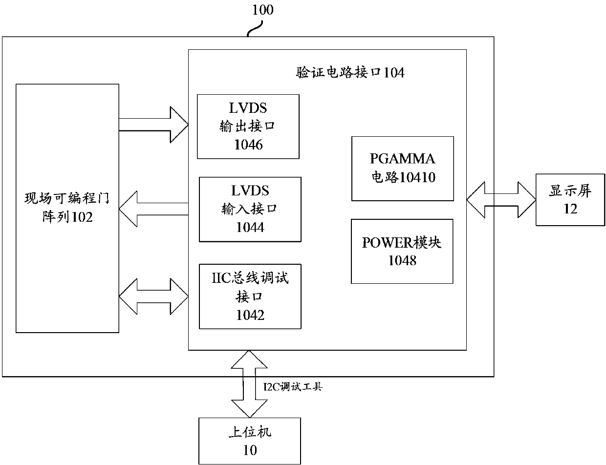
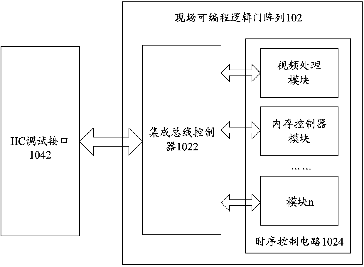
[0014] Combine below figure 1 and figure 2 The verification system of the timing control circuit according to the embodiment of the present invention will be described in detail. figure 1 A schem...


PUM


Abstract

The invention provides a verification system and method of a sequential control circuit. The verification system of the sequential control circuit comprises a field-programmable gate array which is used for setting up the sequential control circuit to be verified and an IIC bus controller. The IIC bus controller is connected to the sequential control circuit and is used for receiving testing instructions from an IIC bus debugging interface and analyzing the testing instructions, and reading-writing operation instructions generated by analyzing are sent to the sequential control circuit. The sequential control circuit receives and executes the reading-writing operation instructions. The verification system further comprises the IIC bus debugging interface which is connected to the IIC bus controller, and the IIC bus debugging interface receives the input testing instructions and transmits the testing instructions to the IIC bus controller. According to the sequential control circuit verification mode based on the field-programmable gate array, the IIC bus controller of hardware is achieved, soft supporting is of no need, a CPU module is of no need, and a quick and convenient debugging method is achieved.

Description

technical field [0001] The invention relates to the technical field of integrated circuits, in particular to a verification system for a timing control circuit and a verification method for a timing control circuit. Background technique [0002] The timing control circuit (TCON) is an important module on the display device, which provides timing control signals for the drive circuits on the display device (such as source drive circuit, gate drive circuit and VCOM polarity control), and processes image data (FRC, OD, etc.), so as to realize the display control of the analog RGB signal. Since different manufacturers and different series of display panels use different source drive circuits and gate drive circuits, the corresponding timing control signals will be different, and the TCON chip must meet the requirements of being compatible with multiple types of display panels. [0003] Before the TCON chip is taped out, the TCON function needs to be verified. During the verifi...

Claims


Application Information

Patent Timeline
Patent Type & Authority Applications(China)
IPC IPC(8): G05B19/042
Inventor 徐卫
Why Eureka
Try Eureka