Converter for linear motion and rotary motion

A technology of rotary motion and linear motion, applied in the field of power transmission, can solve problems such as low efficiency, limited permanent magnet rack and pinion structure, and low torque density, so as to improve reliability, eliminate wear, increase power density and The effect of energy conversion efficiency

Inactive Publication Date: 2013-12-25
SOUTHEAST UNIV
View PDF5 Cites 7 Cited by
  • Summary
  • Abstract
  • Description
  • Claims
  • Application Information

AI Technical Summary

Problems solved by technology

Although the permanent magnet rack and pinion structure can better realize the conversion of the motion form and the adjustment of the motion speed, the torque density it can transmit is small and the efficiency is low, which limits the permanent magnet rack and pinion structure. application of structure

Method used


Image

  • Converter for linear motion and rotary motion
  • Converter for linear motion and rotary motion
  • Converter for linear motion and rotary motion

Examples


Embodiment Construction

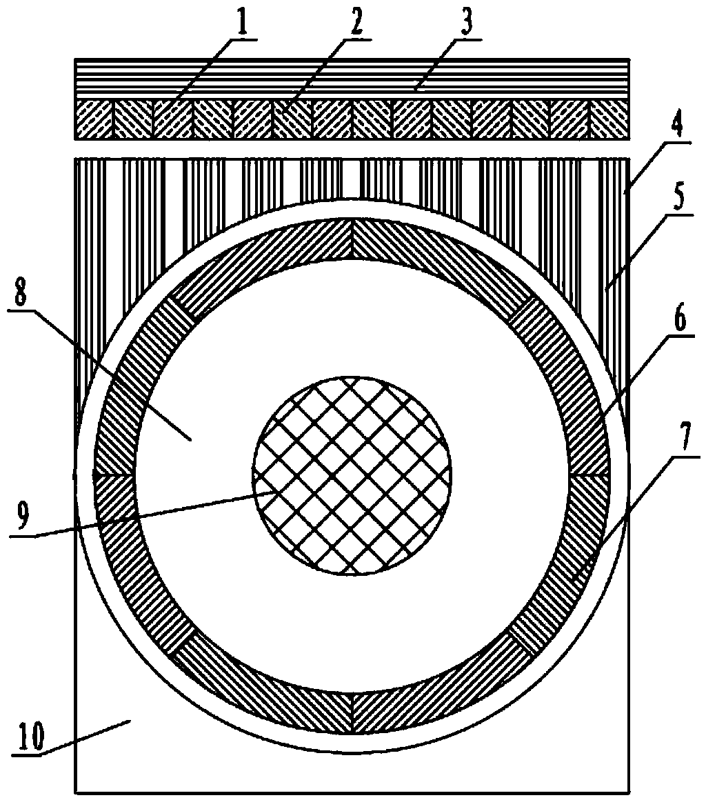
[0029] Below in conjunction with accompanying drawing, the present invention will be further described.

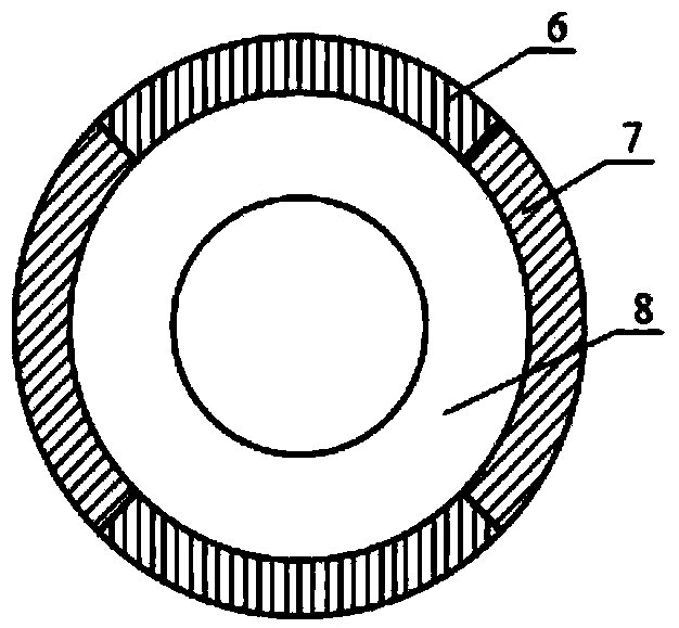
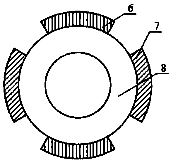
[0030] see figure 1 , the linear motion and rotary motion converter provided by the present invention, the converter includes a casing 10, a magnetic adjustment mechanism placed in the casing 10 and connected to the casing, a rotor arranged in the magnetic adjustment mechanism and a The mover outside the magnetic mechanism; the inner air gap is formed between the magnetic adjustment mechanism and the rotor, and the outer air gap is formed between the magnetic adjustment mechanism and the mover.

[0031] The rotor is connected to the casing 10 through bearings, and freely rotates around the axis. The mover is connected to the casing 10 through guide rails or rollers, and moves in translation along a plane.

[0032] Wherein, the magnetic adjustment mechanism includes magnetic adjustment blocks 4 and non-magnetic conductive filling medium 5; the non-magnetic conductive filli...


PUM


Abstract

The invention provides a converter for linear motion and rotary motion. The converter for the linear motion and the rotary motion comprises a machine shell (10), a magnetism regulation mechanism which is arranged in the machine shell and is connected with the machine shell, a rotor which is arranged in the magnetism regulation mechanism and an active cell which is arranged outside the magnetism regulation mechanism, wherein an inner air gap is formed between the magnetism regulation mechanism and the rotor, an outer air gap is formed between the magnetism regulation mechanism and the active cell, the rotor is connected with the machine shell (10) through a bearing and rotates freely around the axis, the active cell is connected with the machine shell (10) through a guide rail or an idler wheel and moves in a translational mode along a plane, the magnetism regulation mechanism comprises magnetism regulation blocks (4) and non-magnetic packing media (5), the space between every two adjacent magnetism regulation blocks (4) is filled with the non-magnetic packing media (5), and the magnetism regulation blocks (4) and the non-magnetic packing media (5) are arranged integrally in a staggered mode. The converter for the linear motion and the rotary motion has the advantages of being capable of achieving interconversion between the linear motion and the rotary motion and adjusting the relative speed of the linear motion and the rotary motion, free of contact, low in noise, high in efficiency and the like.

Description

technical field [0001] The invention relates to a converter for linear motion and rotary motion, which is suitable for non-contact variable speed driving occasions and belongs to the technical field of power transmission. Background technique [0002] In the fields of industrial and agricultural production, national defense, aviation, aerospace and other fields, it is often necessary to change rotary motion into linear motion, or convert linear motion into rotary motion. According to different applications, people have developed various conversion devices or equipment to meet the above requirements, such as rack and pinion, chain, wire rope, transmission belt, screw rod, crank connecting rod, slider mechanism, cam ejector mechanism, etc. In these conversion devices, the linear motion parts and the rotary motion parts are in contact with each other, which brings problems such as friction, vibration, noise, etc., [0003] Permanent magnet gear is a kind of non-contact transmi...

Claims


Application Information

Patent Timeline
Patent Type & Authority Applications(China)
IPC IPC(8): H02K49/10
Inventor 付兴贺李红艳林明耀赵博
Owner SOUTHEAST UNIV
Why Eureka
Try Eureka