
Welding current source

A technology of welding current and AC voltage source, applied in the field of invention, can solve problems such as large cost, and achieve the effect of low-cost manufacturing

Inactive Publication Date: 2013-12-25
LORCH SCHWEISSTECHNIK GMBH
View PDF3 Cites 0 Cited by
  • Summary
  • Abstract
  • Description
  • Claims
  • Application Information

AI Technical Summary

Problems solved by technology

This is associated with huge costs

Method used


Image

  • Welding current source
  • Welding current source

Examples


Embodiment Construction

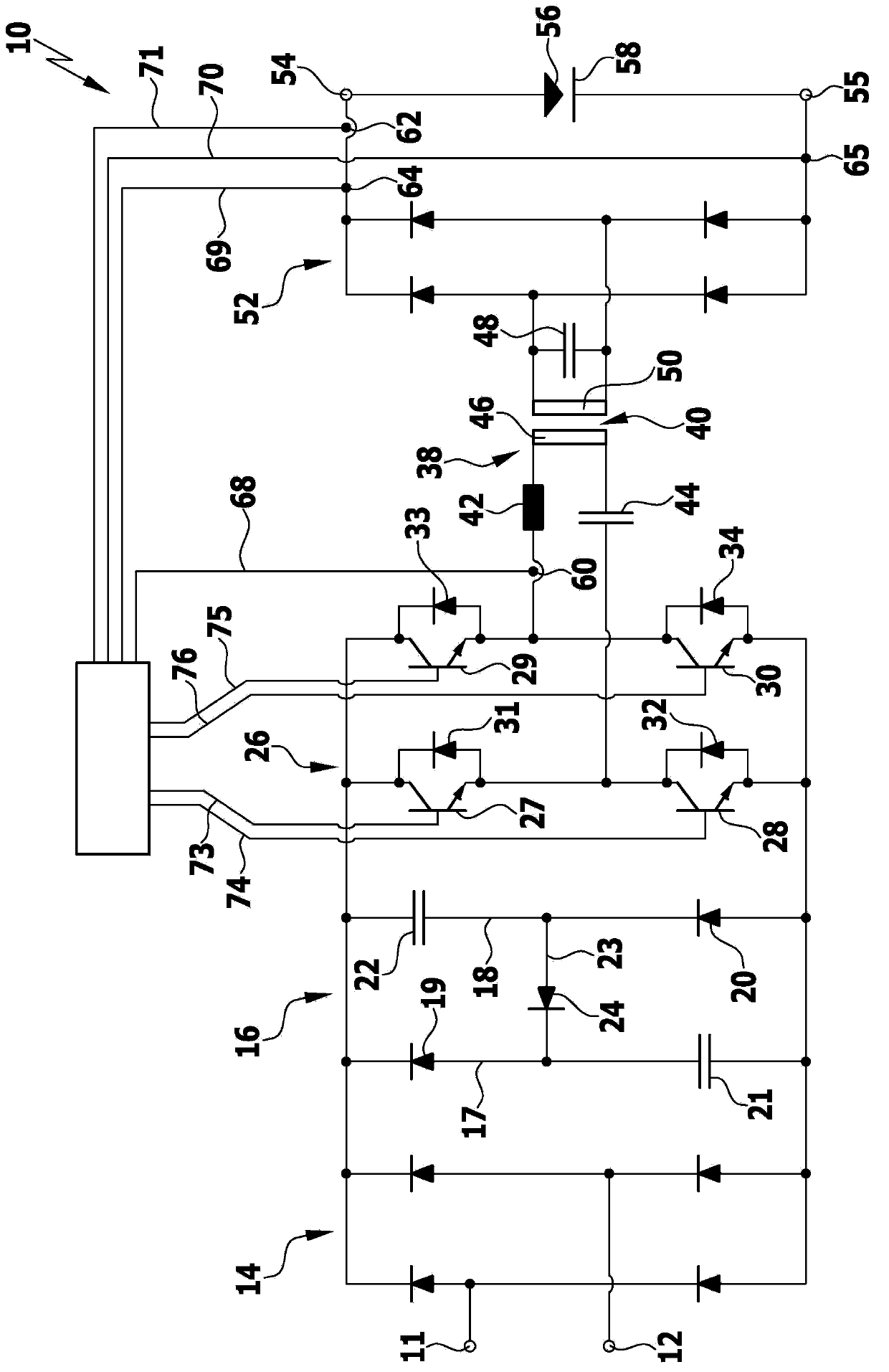
[0024] exist figure 1A simplified block diagram of a welding current source according to the invention is schematically shown in , which is designated as a whole by the reference numeral 10 . It comprises two voltage supply terminals 11 , 12 which can be connected to a single-phase alternating voltage source, in particular to a common voltage supply network. The two voltage supply terminals 11 , 12 form the input of a first rectifier circuit 14 , which in the exemplary embodiment shown is designed as a bridge rectifier. By means of the first rectifier circuit 14 , the single-phase alternating voltage at the supply voltage supply terminals 11 , 12 can be rectified. In order to reduce the ripple of the rectified voltage, a power factor correction circuit 16 is connected to the first rectification circuit 14, which has a first current path 17 and a second current path 18 connected in parallel with the first current path, between the two Connected in each current path is a diode...


PUM


Abstract

The invention relates to a welding current source (10) comprising a first rectifier circuit (14). The input side of the first rectifier circuit is connected with a single-phase alternating current voltage source and the output side of the first rectifier circuit is connected with a clock-controlled bridge type circuit (26) through a passive power factor correction circuit (16). The welding current source is provided with a resonant converter (38) and the resonant converter is provided with a transformer (40) and at least one oscillating circuit. The oscillating circuit comprises at least one capacitor (44) and at least one inductor (42) connected in series with the capacitor. The primary side of the resonant converter is connected with the bridge type circuit (26) and the secondary side of the resonant converter is connected with a second rectifier circuit (52). The output end of the second rectifier circuit can be connected with a welding electrode (56) and a to-be-welded workpiece (58). In order to improve the property of the welding current source, on one hand, the manufacturing cost is lowered. On the other hand, the harmonic load is minimized maximally. In this way, the transformer is connected in parallel with at least one capacitor (48) and / or at least one inductors.

Description

technical field [0001] The invention relates to a welding current source with a first rectifier circuit which can be connected on the input side to a single-phase AC voltage source and which, on the output side, uses a passive power factor The correction circuit is connected to a clock-controlled bridge circuit, and the welding current source has a resonant converter with a transformer and at least one resonant circuit with at least one capacitor and at least one inductor connected in series with the capacitor , and the resonant converter is connected on the primary side to the bridge circuit and on the secondary side to a second rectifier circuit, the output of which can be connected to the welding electrode and the workpiece to be welded. Background technique [0002] Such welding current sources are used in arc welding methods in which an arc burns between a welding electrode and a workpiece so that the arc-side end of the welding electrode melts and the material is trans...

Claims


Application Information

Patent Timeline
Patent Type & Authority Applications(China)
IPC IPC(8): H02M1/42B23K9/10
CPCY02P70/10
Inventor 赫伯特·艾格纳
Owner LORCH SCHWEISSTECHNIK GMBH
Learn More