Feeding device capable of vibrating

A feeding device and material storage technology, which is applied in the field of vibrating feeding devices, can solve the problems of high energy consumption, plastic extruder idling, material blockage, etc., and achieve the effect of ensuring and improving the quality of material conveying

Inactive Publication Date: 2014-01-01
昆山市华浦塑业有限公司
View PDF7 Cites 4 Cited by
  • Summary
  • Abstract
  • Description
  • Claims
  • Application Information

AI Technical Summary

Problems solved by technology

However, due to the accumulation of a large amount of material in the feeding hopper, this feeding method will easily cause the material at the outlet of the feeding hopper to be blocked, forming a "bridging" phenomenon, which will affect the normal feeding of the feeding hopper, thus causing the plastic extruder to break. The material is idling, and the production cannot continue. At the same time, it has a great impact on the service life of the screw and barrel of the plastic extruder. The manufacturer must equip a special person to stir in the hopper, and the feeding effect fluctuates greatly.
However, the existing forced-feeding adopts the spiral downward pressure type, and the screw downward pressure structure is used in the feeding hopper, which not only often gets stuck due to the uneven size of the material, but also consumes a lot of energy during the long-distance screw pressing process. It is easier to cause the temperature in the feeding hopper to rise and make the material sticky and difficult to feed

Method used


Image

  • Feeding device capable of vibrating
  • Feeding device capable of vibrating

Examples


Embodiment Construction

[0020] The technical solutions of the present invention will be further described below in conjunction with the accompanying drawings and through specific implementation methods.

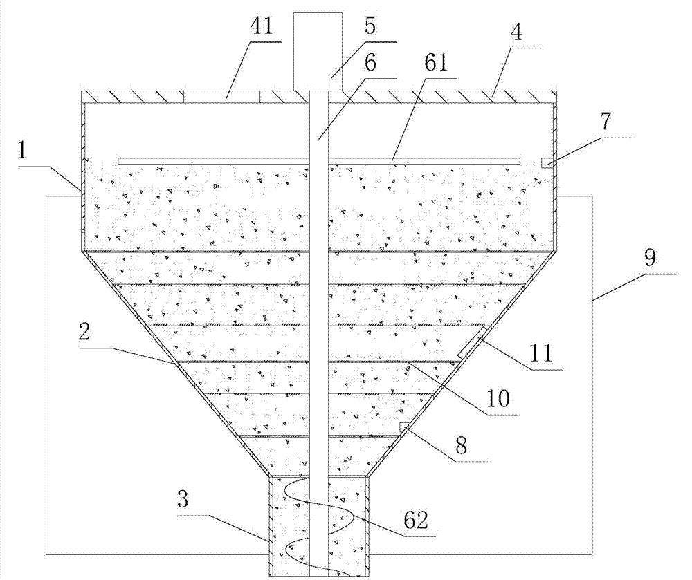
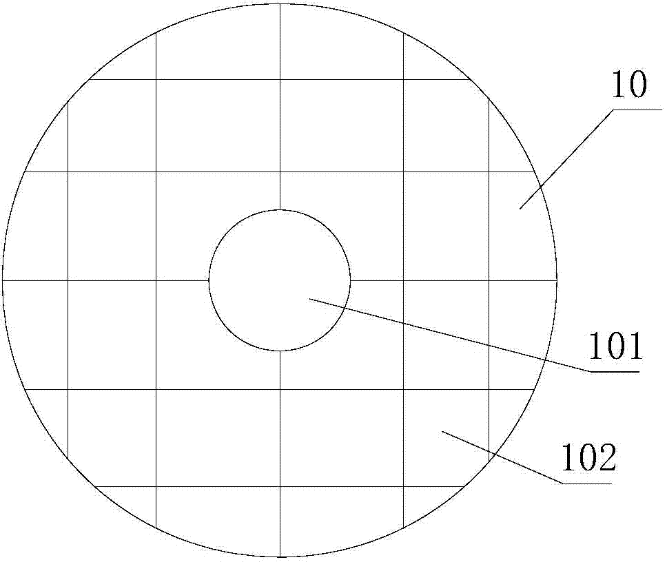
[0021] like figure 1 , figure 2 As shown, a vibrating feeding device includes a bucket body, and the bucket body includes a circular feeding section 1 coaxially arranged, an inverted conical storage section 2 and a circular discharging section 3, The top of the storage section 2 is flexibly connected to the feed section 1, and the bottom end of the storage section 2 is flexibly connected to the discharge section 3. The outer side of the feed section 1 is provided with a frame 9, and the frame 9 is connected to the discharge section 3. External connection; the side wall of the storage section 2 is provided with a vibrator 11, and the storage section 2 is provided with a plurality of detachably connected screens 10 at intervals from top to bottom, and the screen holes 102 of two adjacent screens 10 ...


PUM


Abstract

The invention discloses a feeding device capable of vibrating. The feeding device comprises a bucket body, wherein the bucket body comprises a circular-ring shaped charging section, an inverted cone-shaped material storage section and a circular-ring shaped discharging section which are coaxially arranged; the top end of the material storage section is flexibly connected with the charging section; the bottom end of the material storage section is flexibly connected with the discharging section; a rack is arranged outside the charging section; the rack is connected with the outer side of the charging section; a vibrator is arranged on the side wall of the material storage section; the material storage section is provided with a plurality of screen meshes which are arranged at intervals from top to bottom and are in detachable connection; sieve pores of adjacent two screen meshes are arranged in a staggered manner; shaft through holes are formed at centers of the screen meshes; a cover plate is arranged on the top of the charging section; the cover plate is provided with a charging hole; a drive motor is arranged on the top of the cover plate; the drive motor is connected with a main shaft; the main shaft extends into the bucket body and passes through the shaft through holes to reach the discharging section; a spiral blade is arranged at the tail end of the main shaft; and the spiral blade is arranged in the discharging section. The feeding device capable of vibrating can be used for avoiding material accumulation and is easy for feeding.

Description

technical field [0001] The invention relates to the technical field of extruder equipment, in particular to a vibrating feeding device. Background technique [0002] The host of the plastic extruder is the extruder, which consists of an extrusion system, a transmission system and a heating and cooling system. At present, the automatic metering system is used for feeding the plastic extruder. The plastic and powder are stored in the large feeding hopper, and the stored material is fed to the extrusion equipment through the automatic metering system. In principle, as long as there is material in the feeding hopper, production can be done. Continuous, so keeping the feed hopper filled is critical. The existing feeding hopper has a large volume, and a large amount of materials can be poured in at one time, and enter into the feeding port of the plastic extruder from top to bottom by utilizing the gravity without power. However, due to the accumulation of a large amount of mate...

Claims


Application Information

Patent Timeline
Patent Type & Authority Applications(China)
IPC IPC(8): B29C47/10
CPCB29C48/143B29C48/288
Inventor 吴镇宇
Owner 昆山市华浦塑业有限公司
Why Eureka
Try Eureka