Stop mechanism for transfer gripper in offset press

A technology of stopper mechanism and paper feeding teeth, applied in the general parts of printing machinery, printing presses, printing and other directions, can solve the problems affecting the service life of the swing arm 13 and the swing rod cam 6, the impact vibration of the swing rod cam-spring system, the paper Problems such as adverse effects of handover and transfer, to achieve the effect of being conducive to smooth handover, avoiding shock and vibration, and simple structure

Inactive Publication Date: 2014-01-01
江苏中德包装机械有限公司
View PDF10 Cites 2 Cited by
  • Summary
  • Abstract
  • Description
  • Claims
  • Application Information

AI Technical Summary

Problems solved by technology

[0011] 1. The boss on the swing rod cam 6 is always in contact with the roller on the swing arm 13 through the spring 5. Due to the force change of the spring 5, it is easy to cause shock and vibration of the swing rod cam-spring system, especially when running at high speed. Adversely affect paper delivery;
[0012] 2. The structure of the swing rod cam 6 is complex, that is, there are two working surfaces (such as Figure 2b As shown in the curved groove Ⅰ, and the boss Ⅱ), it is difficult to guarantee the machining accuracy, which makes the machining cost higher
[0013] 3. When the paper feeding is abnormal, the boss working surface II of the swing lever cam 6 cannot always contact the roller on the swing arm 13, and the roller on the swing arm 13 will inevitably make the boss working surface of the swing lever cam 6 The impact phenomenon of II affects the service life of the roller on the swing arm 13 and the swing cam 6, and affects the accuracy and stability of paper transfer during high-speed printing

Method used


Image

  • Stop mechanism for transfer gripper in offset press
  • Stop mechanism for transfer gripper in offset press
  • Stop mechanism for transfer gripper in offset press

Examples


Embodiment Construction

[0037] In order to better understand the technical solutions of the present invention, specific embodiments will be described in detail below in conjunction with the accompanying drawings.

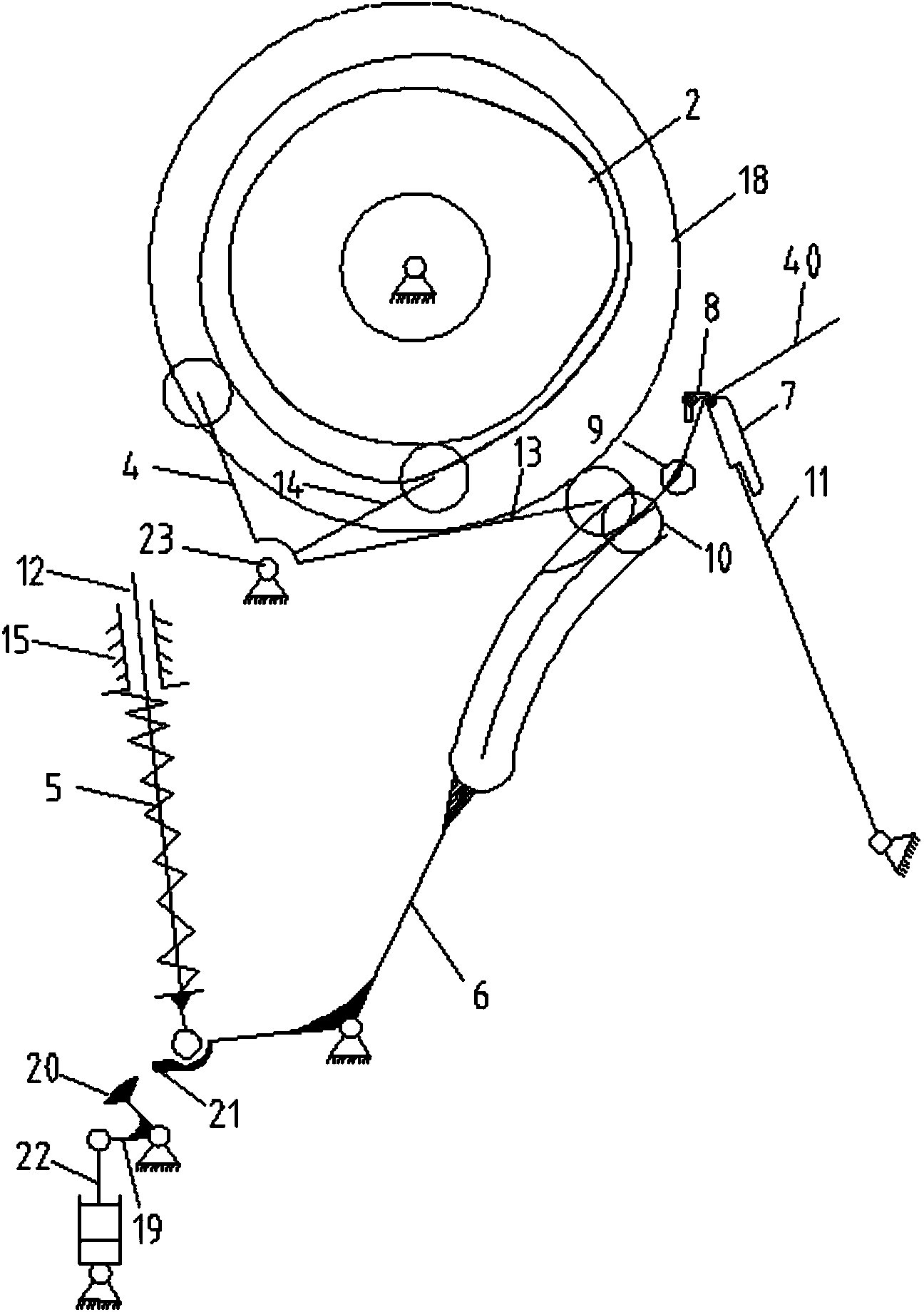
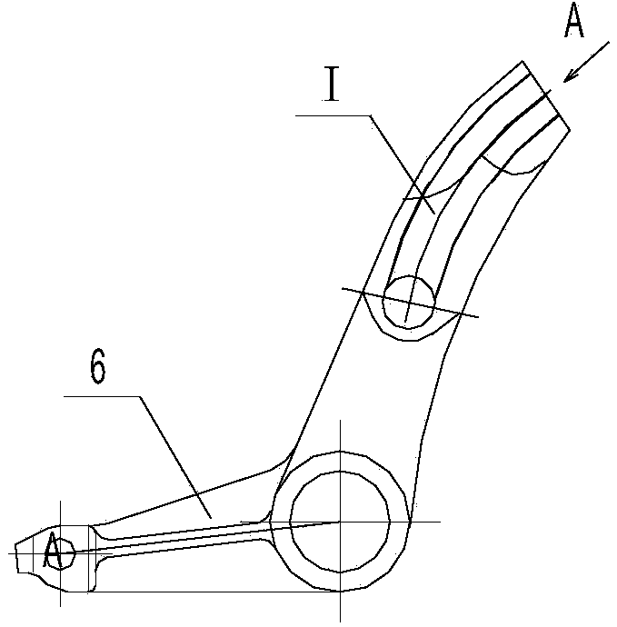
[0038] see Figure 3 to Figure 5c , a stop mechanism for the paper delivery teeth of an offset printing press of the present invention, including a paper delivery cylinder 26 bridged between the driving side wallboard 29 and the operation side wallboard of the offset printing machine, a paper delivery hand, and a teeth opening and closing mechanism and protection agencies.

[0039] The transfer cylinder 26 is bridged between the driving side wallboard 29 and the operating sidewallboard of the offset printing machine; a cover-type support frame 30 is installed on the outside of the driving sidewallboard 29; Shaped bracket 28; the driving side shaft head of the paper transfer cylinder 26 passes through the driving side wall plate 29 and is installed on the bottom plate of the support frame ...


PUM


Abstract

The invention discloses a stop mechanism for a transfer gripper in an offset press. The stop mechanism comprises a transfer roller, a transfer arm, a gripper opening and closing mechanism, and a protection mechanism. The gripper opening and closing mechanism comprises a driving gear, a gripper opening and closing control cam, a pair of driving swing bars, and a swing bar cam, wherein the driving gear and the gripper opening and closing control cam are fixedly mounted on a drive side shaft end of the transfer roller, one end of each driving swing bar is fixedly mounted on a swing bar shaft and the swing bar cam is mounted on a camshaft. The protection mechanism comprises a stop cylinder mounted on the inner side of a transmission side wallboard, a V-shaped swing bar, a stop link and a stop swing bar. The V-shaped swing bar is rotatably mounted on the inner side of a drive side wallboard through a pile head. One end of the V-shaped swing bar is hinged to a piton rod of the stop cylinder, and the other end of the V-shaped swing bar is hinged to one end of the stop link. The other end of the stop link is hinged to one end of the stop swing bar. The other end of the stop swing bar is fixed to the camshaft. The stop mechanism is capable of avoiding waste paper in case of an anomaly of paper on a discharge board.

Description

technical field [0001] The present invention relates to an offset printing machine, in particular to a stop mechanism of the paper delivery teeth of the offset printing machine, which is used for preventing abnormal paper from entering the printing when the paper feeding mechanism is abnormal. purpose of the unit. Background technique [0002] The paper transfer mechanism in the offset printing machine is divided into three categories according to the route of the paper transfer: direct paper transfer, indirect paper transfer and beyond the continuous paper. [0003] Direct paper transfer is the way that the paper is directly picked up by the tooth row on the impression cylinder after the paper feeding board is positioned. [0004] Indirect paper transfer means that after the paper is positioned on the paper feeding board, it is first picked up by the tooth row of the paper delivery mechanism, and then delivered to the tooth row on the impression cylinder by the paper deliv...

Claims


Application Information

Patent Timeline
Patent Type & Authority Applications(China)
IPC IPC(8): B41F21/04
Inventor 乔俊伟肖虎
Owner 江苏中德包装机械有限公司
Why Eureka
Try Eureka