
Wireless temperature sensing system capable of collecting radio frequency energy and energy control method

A wireless temperature and radio frequency energy technology, applied in signal transmission systems, thermometers, measuring heat and other directions, can solve the problems of limited service life and narrow adaptation surface of wireless sensors, achieve strong adaptability and self-adjustment ability, reduce size, improve The effect of job stability

Active Publication Date: 2014-01-01
BEIJING SMARTCHIP MICROELECTRONICS TECH COMPANY +1
View PDF5 Cites 6 Cited by
  • Summary
  • Abstract
  • Description
  • Claims
  • Application Information

AI Technical Summary

Problems solved by technology

[0004] The present invention mainly solves the technical problems of limited service life and narrow adaptable surface of wireless sensors existing in the prior art, and provides a wireless sensor with a very long service life, which can work in environments such as small temperature difference and no vibration, and has a certain Radio Frequency Energy Harvesting Wireless Temperature Sensing System and Energy Control Method with Self-adjusting Capability to Maintain Working State as Much as Possible

Method used


Image

  • Wireless temperature sensing system capable of collecting radio frequency energy and energy control method
  • Wireless temperature sensing system capable of collecting radio frequency energy and energy control method
  • Wireless temperature sensing system capable of collecting radio frequency energy and energy control method

Examples


Embodiment

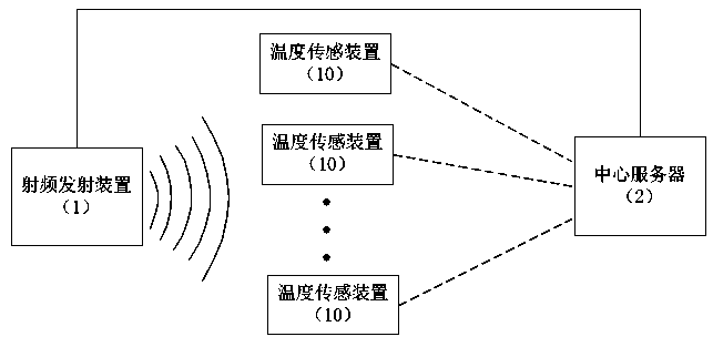
[0042] Embodiment: a kind of radio frequency energy harvesting wireless temperature sensing system of this embodiment, such as figure 1 As shown, it includes a radio frequency transmitting device 1 , a central server 2 and several temperature sensing devices 10 . The radio frequency transmitting device 1 includes a power control module, a radio frequency transmitter and an electric steering mechanism, and the radio frequency transmitter is connected to a power supply through the power control module; both the power control module and the electric steering mechanism are connected to the central server 2 . The radio frequency transmitter is arranged on the electric steering mechanism, and the emission angle can be changed under the driving of the electric steering mechanism.

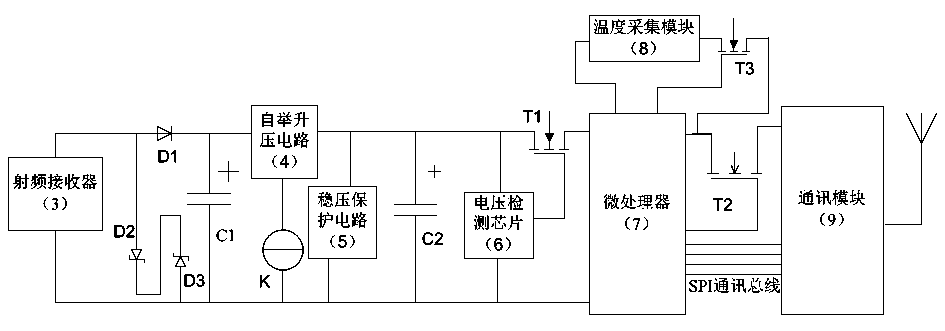
[0043] Such as figure 2 As shown, the temperature sensing device includes a temperature acquisition module 8, a microprocessor 7, a communication module 9, and a power supply module. The communication m...


PUM


Abstract

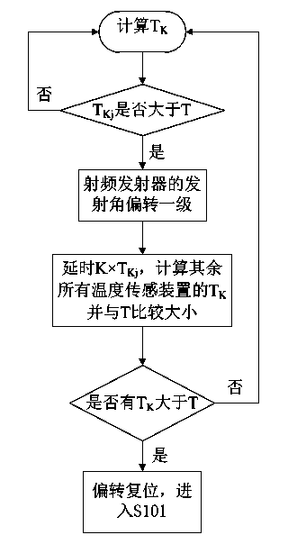
The invention discloses a wireless temperature sensing system capable of collecting radio frequency energy and an energy control method. The wireless temperature sensing system capable of collecting the radio frequency energy comprises a radio frequency emitting device, a central server and a plurality of temperature sensors. The radio frequency emitting device comprises a power control module and a radio frequency emitter, wherein the radio frequency emitter is connected with a power source through the power control module. The power control module is connected with the central server. The radio frequency emitting device transmits energy to the temperature sensors in a radio frequency mode. The central server judges the energy collection condition by the temperature sensors according to received data. When the energy collected by the temperature sensors is insufficient, the emission power of the radio frequency emitter is increased through the power control module, and normal work of the temperature sensors is maintained. When the power of the radio frequency emitter reaches the limit value, the radio frequency emitter reaches the Q state to operate, and data collected for multiple times are sent for one time. The wireless temperature sensing system capable of collecting the radio frequency energy has the certain self-adjusting capacity, can maintain the work state to the greatest extent, and is suitable for the fields, such as the electric power field, needing temperature measurement.

Description

technical field [0001] The invention relates to a wireless sensing device, in particular to a wireless temperature sensing system and an energy control method for collecting radio frequency energy without transmission cables. Background technique [0002] For the current wireless temperature measurement technology, most of the temperature measurement products are powered by batteries or CTs. There is a service life problem in the use of the battery. After a period of use, the battery needs to be replaced when the battery is exhausted, and the leakage and explosion of the battery will cause potential safety hazards. However, CT has the problems of large volume and inconvenient installation, and it will generate vibration and heat in the super-strong magnetic field, which will cause serious harm to power equipment. [0003] The State Intellectual Property Office of the People's Republic of China published a patent document with the authorized announcement number CN201145943Y ...

Claims


Application Information

Patent Timeline
IPC IPC(8): G01K1/02H02J17/00G08C17/02G01K1/024H02J50/00
Inventor 王龙吴孝兵赵国栋滕明茂
Owner BEIJING SMARTCHIP MICROELECTRONICS TECH COMPANY
Learn More