
Passive containment vessel spraying device

A passive containment and spray device technology, applied in cooling devices, nuclear power generation, reactors, etc., can solve problems such as high engineering cost and maintenance cost, unfavorable anti-seismic shielding plant, and inability to eliminate the effect of water flow grooves, etc., to achieve improved Safety and economy, low cost and maintenance cost, and the effect of eliminating the effect of water flow grooves

Inactive Publication Date: 2014-01-01
NUCLEAR POWER INSTITUTE OF CHINA
View PDF9 Cites 19 Cited by
  • Summary
  • Abstract
  • Description
  • Claims
  • Application Information

AI Technical Summary

Problems solved by technology

[0003] At present, most common nuclear power plants in the world use active pumps to drive spraying devices to cool down the inside of the containment by spraying water to reduce the temperature and pressure. Safety-level emergency power supplies must be equipped. Short-term and long-term cooling of the containment when multiple extreme accidents such as plant power outages are superimposed
[0004] The passive containment cooling system of AP1000 unit developed by Westinghouse Company in the United States relies on gravity spraying to cool the steel containment through the high-level water tank installed on the shielded building, but it has the following disadvantages: ①The 3000-ton high-level water tank makes the shielded building anti-seismic due to the liquid-solid coupling effect It brings extremely adverse effects and high engineering cost; ②The steel containment cooling system is equipped with a huge and complicated water flow distribution system and air diversion structure, and the project cost and maintenance cost are high; ③Although the water flow distribution structure is adopted, the water flow cannot be eliminated. Due to the groove effect, it is impossible to achieve uniform coverage of the water film on the surface of the containment vessel, and a considerable part of the surface of the containment vessel is in a dry state, unable to conduct heat

Method used


Image

  • Passive containment vessel spraying device
  • Passive containment vessel spraying device

Examples


Embodiment Construction

[0013] The present invention will be described in detail below in conjunction with the accompanying drawings and specific embodiments.

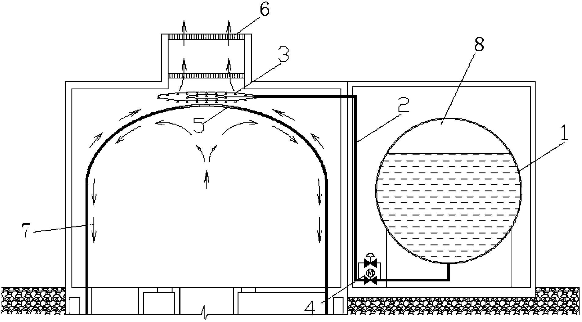
[0014] Such as figure 1 As shown, a passive containment spraying device includes a steel spherical safety spray box 1 filled with water and compressed air 8, and the safety spray box 1 is connected to the annular spray collection through a water pipeline 2 The pipe 3 and the annular spray header 3 are arranged above the containment dome 5, and a normally closed valve group 4 is installed between the water delivery pipeline 2 and the annular spray header 3, wherein the normally closed valve group 4 includes parallel One electric ball valve and one manual valve.

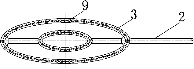
[0015] Such as figure 2 As shown, the annular spraying header 3 includes 2 rings of ring-shaped shower pipes, each ring of ring-shaped shower pipes is connected to the water delivery pipeline 2, and a plurality of overflow holes 9 are opened on the ring-shaped shower pipes.

[001...


PUM


Abstract

The invention belongs to a device for spraying and cooling of the outer surface of a containment vessel in a passive mode, and particularly relates to the nuclear reactor containment vessel spraying and cooling device. The passive containment vessel spraying device comprises a safe spraying box, the safe spraying box is connected with an annular spraying header through a water transmission pipeline, the annular spraying header is arranged above a containment vessel dome, and a normally closed valve assembly is arranged between the water transmission pipeline and the annular spray header. The passive containment vessel spraying device has the advantages that the passive containment vessel spraying device is different from an active containment vessel interior spraying system of a conventional nuclear power plant and adopts an external spraying mode, does not need a safety-level emergency power supply and active components, and can realize short-term and long-term cooling of the containment vessel during superposition of a reactor loss-of-coolant accident or a main steam pipeline fracture accident with a station blackout accident and other superposition of multiple extreme accidents.

Description

technical field [0001] The invention belongs to a device for spraying and cooling the outer surface of a containment vessel in a passive manner, in particular to a device for spraying and cooling the containment vessel of a nuclear reactor. Background technique [0002] As a special safety facility for nuclear power plants, the containment can protect the reactor from the hazards of external events. After the accident, as the last barrier of nuclear reactor radioactivity containment, it can protect the environment and the public from excessive radiation. When a reactor loses water accident or a main steam pipe rupture accident occurs, a large amount of mass energy is released into the containment vessel, causing the temperature and pressure of the containment vessel to rise rapidly. In order to prevent over-temperature and over-pressure of the containment, the heat of the containment must be exported in time. [0003] At present, most common nuclear power plants in the worl...

Claims


Application Information

Patent Timeline
IPC IPC(8): G21C15/18
CPCY02E30/40Y02E30/30
Inventor 秦忠宋丹戎许斌李庆
Owner NUCLEAR POWER INSTITUTE OF CHINA
Learn More