A kind of manufacturing equipment for self-adhesive glass fiber-wrapped composite film wrapping electromagnetic wire

A technology of composite film and manufacturing equipment, applied in cable/conductor manufacturing, circuit, insulated cable, etc., can solve problems such as low efficiency and long production line, and achieve the effect of improving production efficiency, compact equipment structure, and shortening operating distance

Active Publication Date: 2016-04-06
SUZHOU GUANLONG MAGNET WIRE
View PDF6 Cites 0 Cited by
  • Summary
  • Abstract
  • Description
  • Claims
  • Application Information

AI Technical Summary

Problems solved by technology

[0002] Electromagnetic wire manufacturing equipment in the prior art usually includes a pay-off rack, a meter counting device for counting the wires, a straightening device for straightening the wires, and a straightening device for removing the wires. A polishing device for burrs on the wire, a cleaning device for cleaning the wire, an air-drying device for air-drying the wire, a film wrapping device for wrapping a film on the wire , an induction heating device for heating the electromagnetic wire, a rolling device for rolling the heated electromagnetic wire, an oven, a water-cooled drying device for cooling the rolled electromagnetic wire, and a The traction device and the wire take-up machine for pulling the electromagnetic wire described above, however, its pay-off rack and wire take-up machine are usually located on both sides of the equipment, making the production line longer; and if the self-adhesive glass fiber wrapped composite film is to be wrapped When the electromagnetic wire is produced, it is necessary to heat-seal the wire by wrapping the composite film and take it up, and then wrap the wire and dip it in paint and bake it. Two-step production is required, and the efficiency is low.

Method used


Image

  • A kind of manufacturing equipment for self-adhesive glass fiber-wrapped composite film wrapping electromagnetic wire
  • A kind of manufacturing equipment for self-adhesive glass fiber-wrapped composite film wrapping electromagnetic wire
  • A kind of manufacturing equipment for self-adhesive glass fiber-wrapped composite film wrapping electromagnetic wire

Examples


Embodiment 1

[0024] Embodiment 1: Production of small gauge magnet wire

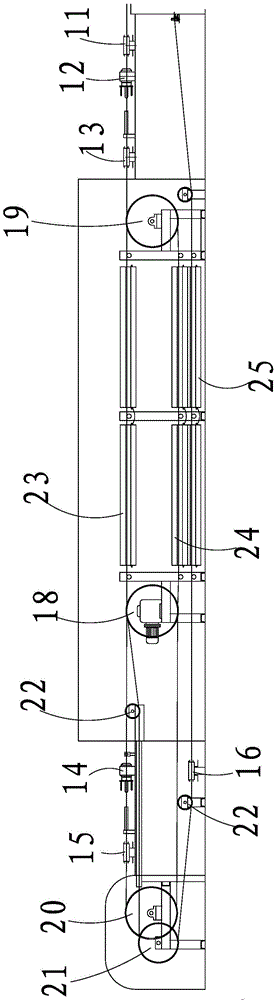
[0025] as attached figure 2 As shown, the traction device includes a driving wheel 18 positioned between one end of the oven assembly and the second glass wool head 14, a driven wheel 19 positioned between the other end of the oven assembly and the second paint vat 13, and a third paint vat located between 15 and the first guide wheel 20 and the second guide wheel 21 between the self-adhesive coating paint vat 16, and a plurality of bridge wheels 22 for changing the direction of the electromagnetic wire. There are 2 bridge wheels 22, and a bridge wheel 22 is positioned between the driving wheel 18 and the second glass fiber toe cap 14, and another bridge wheel 22 is positioned between the second guide wheel 21 and the self-adhesive coating paint vat 16.

[0026] The oven assembly includes a first main oven 23 and a second main oven 24 for baking the dipped magnet wire, and an auxiliary oven 25 for baking the magnet...

Embodiment 2

[0029] Example 2: Production of medium-grade gauge magnet wire

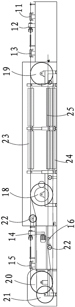
[0030] as attached image 3 As shown, the traction device includes a driving wheel 18 positioned between one end of the oven assembly and the second glass wool head 14, a driven wheel 19 positioned between the other end of the oven assembly and the second paint vat 13, and a third paint vat located between 15 and the first guide wheel 20 and the second guide wheel 21 between the self-adhesive coating paint vat 16, and a plurality of bridge wheels 22 for changing the direction of the electromagnetic wire. There are 2 bridge wheels 22, and a bridge wheel 22 is positioned between the driving wheel 18 and the second glass fiber toe cap 14, and another bridge wheel 22 is positioned between the second guide wheel 21 and the self-adhesive coating paint vat 16.

[0031] The oven assembly includes a first main oven 23 and a second main oven 24 for baking the dipped magnet wire, and an auxiliary oven 25 for baking the mag...

Embodiment 3

[0034] Embodiment 3: Production of large wire gauge magnet wire

[0035] as attached Figure 4 As shown, the traction device includes a driving wheel 18 positioned between one end of the oven assembly and the second glass wool head 14, a driven wheel 19 positioned between the other end of the oven assembly and the second paint vat 13, and a third paint vat located between 15 and the first guide wheel 20 and the second guide wheel 21 between the self-adhesive coating paint vat 16, and a plurality of bridge wheels 22 for changing the direction of the electromagnetic wire. There are 3 bridge wheels 22, one bridge wheel 22 is located between the driving wheel 18 and the second glass fiber cap 14, and the other 2 bridge wheels 22 are located between the second guide wheel 21 and the self-adhesive coating paint vat 16 .

[0036] The oven assembly includes a first main oven 23 and a second main oven 24 for baking the dipped magnet wire, and an auxiliary oven 25 for baking the magne...


PUM


Abstract

The invention relates to equipment for manufacturing self-adhesive glass silk covered composite film lapping electromagnetic wires. The equipment comprises a pay-off rack, a meter counting device, a straightening device, a polishing device, a cleaning device, an air drying device, a film lapping device, an induction heating device, a rolling device, a water cooling blow-drying device, a traction device and a take-up machine. The equipment further comprises a first paint cylinder, a first glass silk covered head, a second paint cylinder, a second glass silk covered head, a third paint cylinder, a self-adhesive coating paint cylinder and a drying oven assembly. The pay-off rack and the take-up machine are located on the same side. The equipment is compact in structure. With the cooperation with the intensive requirement, operation quality control points are relatively centralized, the operation distance is beneficially shortened, and production efficiency is improved. The self-adhesive glass silk covered composite film lapping electromagnetic wires can be formed on the production equipment at one time, and therefore production efficiency is improved.

Description

technical field [0001] The invention relates to a kind of manufacturing equipment for self-adhesive glass fiber-wrapped composite film wrapping electromagnetic wire. Background technique [0002] Electromagnetic wire manufacturing equipment in the prior art usually includes a pay-off rack, a meter counting device for counting the wires, a straightening device for straightening the wires, and a straightening device for removing the wires. A polishing device for burrs on the wire, a cleaning device for cleaning the wire, an air-drying device for air-drying the wire, a film wrapping device for wrapping a film on the wire , an induction heating device for heating the electromagnetic wire, a rolling device for rolling the heated electromagnetic wire, an oven, a water-cooled drying device for cooling the rolled electromagnetic wire, and a The traction device and the wire take-up machine for pulling the electromagnetic wire described above, however, its pay-off rack and wire take-...

Claims


Application Information

Patent Timeline
Patent Type & Authority Patents(China)
IPC IPC(8): H01B7/00H01B13/00H01B13/26
Inventor 郑一帆
Owner SUZHOU GUANLONG MAGNET WIRE
Why Eureka
Try Eureka