Message switching system and message switching method based on ultrasonic waves

An information exchange and ultrasonic technology, applied in the field of information processing, can solve the problems of remote verification of geographic location data, high cost of positioning technology equipment, lack of security, etc. Low configuration requirements

Inactive Publication Date: 2014-01-01
上海君戈网络科技有限公司
View PDF1 Cites 14 Cited by
  • Summary
  • Abstract
  • Description
  • Claims
  • Application Information

AI Technical Summary

Problems solved by technology

The disadvantage of this invention is that the mobile terminal can only demodulate the data preset in the ultrasonic generator, and cannot obtain the latest service information and points and other data in real time, and the geographic location data sent by the ultrasonic generator cannot be obtaine

Method used


Image

  • Message switching system and message switching method based on ultrasonic waves
  • Message switching system and message switching method based on ultrasonic waves
  • Message switching system and message switching method based on ultrasonic waves

Examples


Embodiment 1

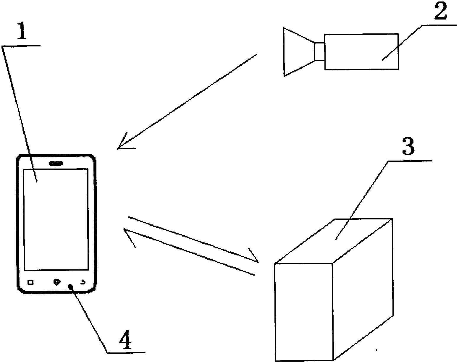
[0026] Embodiment 1: as figure 1 As shown, this embodiment relates to information processing technology, and specifically relates to an indoor small-scale and high-precision ultrasonic-based information exchange system and its exchange method. The information exchange system is mainly composed of a mobile terminal 1 , an ultrasonic transmitter 2 and a server 3 . Each ultrasonic emitting device 2 is assigned a different equipment code and location identification code, and there is a specific encryption operation relationship between these two codes. When the ultrasonic transmitting device 2 sends out an ultrasonic signal with preset information, the existing microphone 4 on the mobile terminal 1 receives the ultrasonic signal, and completes the decoding of the ultrasonic signal through a demodulation module, thereby knowing that the ultrasonic transmitting device 2 Afterwards, the mobile terminal 2 sends the location code to the server 3 through the wireless network or the mob...

Embodiment 2

[0038] In this embodiment, indoor small-scale positioning is preferably realized through the ultrasonic emitting device 2 and the server 3 . Embodiment 2: as Figure 4 Shown is the working principle diagram of the preferred ultrasonic amplifier of the present invention, through digital switching devices, such as circuits such as 4069 to realize a differential drive, its specific working principle is as follows:

[0039] ① The data modulation signal to be amplified is input from pin 13 of U1F;

[0040] ② A reverse analog amplification of about 10 times is completed through U1F and transmitted to pin 11 of U1E;

[0041] ③U1E works in the switch state, realizing a signal reverse action;

[0042] ④U1A and U1B complete the in-phase amplification of the signal;

[0043] ⑤ U1C and U1D complete the inverse amplification of the signal;

[0044] ⑥LS1 is a piezoelectric ceramic speaker driven by a digital differential circuit composed of U1A, U1B, U1C, and U1D;

[0045] ⑦ R111 and R...


PUM


Abstract

The invention relates to the information processing technology, in particular to an indoor small-range and high-precision message switching system and message switching method based on ultrasonic waves. According to the technical scheme, the message switching system is composed of an ultrasonic wave emitting device, a mobile terminal and a server, the ultrasonic wave emitting device is arranged at the specific position and is used for sending an ultrasonic wave signal which is modulated in advance and comprises an equipment code and a position recognition code. A microphone on the mobile terminal is used for receiving ultrasonic waves and decoding the ultrasonic waves into the equipment code and the position code and sending the equipment code and the position code to the server through the mobile network, and the server acquiring the codes pushes the position service information to the mobile terminal immediately. The message switching system has the advantages that the message switching system is safe, reliable and high in anti-fake performance, users of the mobile terminal can locate and obtain the surrounding service information at any time, the requirement for the hardware configuration of the mobile terminal is low, the ultrasonic wave emitting device is low in construction cost, and the message switching system is suitable for being popularized in a large scale.

Description

technical field [0001] The invention relates to information processing technology, in particular to an indoor small-scale and high-precision ultrasonic-based information exchange system and an exchange method thereof. Background technique [0002] With the development of information and communication technology and the popularization of smart phones, the positioning technology of mobile terminals is also showing a trend of diversification, which brings unlimited business opportunities to the development and expansion of location services. The so-called location service (LBS, Location Based Services), also known as location service, refers to the cooperation between the mobile terminal and the mobile network to determine the actual geographical location of the mobile user, thereby providing the location-related service information and point rewards required by the user. a form. [0003] At present, the positioning technology of mobile terminals mainly includes: positioning b...

Claims


Application Information

Patent Timeline
IPC IPC(8): H04B11/00
Inventor 毛洁明曲映晖
Owner 上海君戈网络科技有限公司
Why Eureka
Try Eureka