Device for transmitting force

A technology of equipment and transmission mechanism, applied in the field of force transmission equipment, can solve problems such as complex structure, and achieve the effect of compact structure, simple and compact equipment structure, and compact structure

Active Publication Date: 2014-01-01
VOITH PATENT GMBH
View PDF9 Cites 11 Cited by
  • Summary
  • Abstract
  • Description
  • Claims
  • Application Information

AI Technical Summary

Problems solved by technology

The structure is correspondingly complex, since here the task is quite different, namely to convert the variable input speed into the appropriate transmission gear / gear ratio as required

Method used


Image

  • Device for transmitting force

Examples


Embodiment Construction

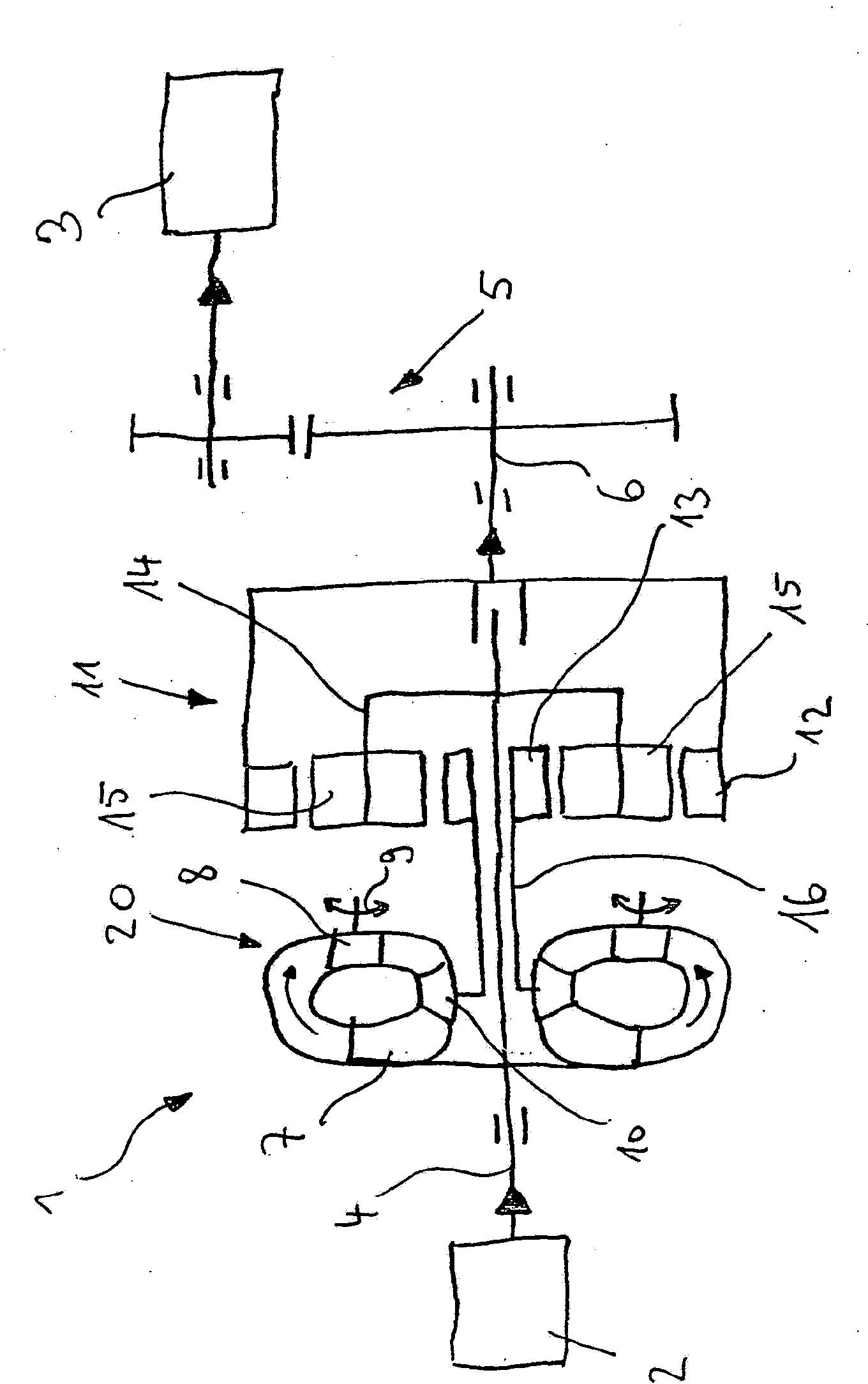
[0014] In the single figure, a device 1 for power transmission is shown, which connects a drive unit 2 and a working machine 3 to one another. In this case, the drive assembly 2 can be designed in particular as a motor, particularly preferably as an electric motor. In the construction shown here, this typically provides a constant rotational speed at which the drive assembly drives the input shaft 4 , which is connected to the drive directly or optionally also via a transmission stage not shown. Component connections. A work machine 3 is then driven via the device 1 , which is designed as a work machine 3 with a variable rotational speed. The work machine 3 can in particular be a compressor or air compressor, a centrifugal pump or the like. In the exemplary embodiment shown here, the working machine is indirectly connected via a spur gear 5 to an output shaft 6 . A connection via a planetary gear, bevel gear or the like is likewise conceivable. The device 1 for power trans...


PUM


Abstract

The invention relates to a device (1) for transmitting force from an input shaft (4) connected to a drive assembly (2) having constant speed to an output shaft (6) connected to a working machine (3) having variable speed, comprising: a hydrodynamic transducer (20); and a differential transmission designed as a planetary gear unit (1), comprising a ring gear (12), a sun gear (13) and a planet carrier (14) having a plurality of planets (15) as elements of the planetary gear unit. The invention is characterised in that: the hydrodynamic transducer is designed as a counter-movement transducer; the input shaft is directly connected to a pump impeller (7) of the hydrodynamic transducer and a first element (14) of the planetary gear unit; a turbine wheel (10) of the hydrodynamic transducer is directly connected to a second element (13) of the planetary gear unit, and the output shaft is connected at least indirectly to a third element of the planetary gear unit.

Description

technical field [0001] The invention relates to a device for force transmission as defined in detail in the preamble of claim 1 . Background technique [0002] A force transmission assembly for driving a variable-speed working machine is known from DE 34 41 877 A1. The power transmission assembly consists of a gear with a planetary gear, wherein the power branch is divided into a mechanical power branch and a hydraulic power branch. The hydraulic power branch runs through the torque converter and its rotational speed can be adjusted via the torque converter. The hydraulic power branch is recombined with the mechanically transmitted power branch in the planetary gear and thus drives the working machine at the desired rotational speed, although the drive unit driving the power transmission unit on the input shaft operates at a constant rotational speed. The structure described in the German patent document with a concentrically extending shaft is realized here in a relativel...

Claims


Application Information

Patent Timeline
Patent Type & Authority Applications(China)
IPC IPC(8): F16H47/08
CPCF16H47/085F16H2037/088F16H47/08F16H47/06F16H41/24
Inventor 哈特穆特·格拉夫
Owner VOITH PATENT GMBH
Why Eureka
Try Eureka