Winding machine

A winding machine and winding rod technology, which is applied in the field of winding machines, can solve the problems of high wire cost, poor product uniformity, and high defect rate, and achieve the effects of reducing labor intensity, improving production efficiency, and uniform tightness

Active Publication Date: 2014-01-08
昆山奥泰克自动化科技有限公司
View PDF9 Cites 6 Cited by
  • Summary
  • Abstract
  • Description
  • Claims
  • Application Information

AI Technical Summary

Problems solved by technology

[0002] Most of the existing wire winding is manual winding, and a small part is semi-manual winding. The pitch, tightness and number of turns of the wire harness are all manually controlled. This semi-manual control equipment has low efficiency, poor product uniformity, and a high defect rate. High, and has a certain degree of danger, which may hurt the operator. With the improvement of customer quality requirements and the increase of material costs, the cost of manual or semi-manual winding wire is getting higher and higher, and the profit of manufacturers is plummeting.

Method used


Image

  • Winding machine
  • Winding machine
  • Winding machine

Examples


Embodiment 1

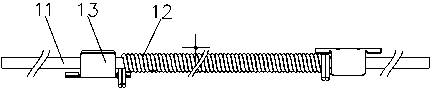
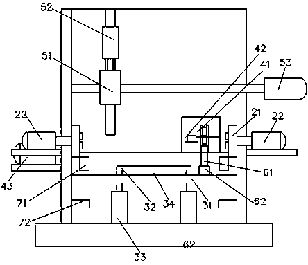
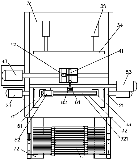
[0030] see Figure 1-Figure 4 , as shown in the legend therein, a winding machine is used to wind the wire 12 on the winding rod 11 and make the wire clamp 13 clamp the wire 12 to form the spring wire rod 1 on the winding rod 11, the above The wire winding machine includes a winding reel mechanism, a rod advancing mechanism, a wire releasing mechanism, a clamping mechanism, a cutting mechanism, a retracting rod mechanism and a control device.

[0031] The above-mentioned reel mechanism includes a symmetrically arranged reel, which includes a clamping disc 21 for clamping the reel rod, a first coil for axially moving the clamping disc 21 Wire driving device (not shown in the figure) and a second winding driving device 22 for making the clamping disc 21 rotate circumferentially; the clamping disc 21 is provided with a clamping hole extending along its axial centerline 211 and several advancing and retreating rod grooves 212 extending radially and communicating with the clamping...

Embodiment 2

[0050] The rest is the same as the above-mentioned embodiment 1, the difference is that the above-mentioned winding machine also includes a chassis, and the above-mentioned winding reel mechanism, rod-entry mechanism, wire-paying mechanism, clamping mechanism, cutting mechanism and retracting rod mechanism are built into the chassis; The above-mentioned control device is placed outside the chassis.

[0051] The setting of the chassis can make the winding be carried out in a confined space, and there will be no potential safety hazard.

Embodiment 3

[0053] The rest is the same as that of Embodiment 2, the difference is that the above-mentioned winding machine also includes a winding rod warehouse for storing multiple winding rods and a wire clip warehouse for storing multiple wire clips, and the wire clip warehouse is set There is a screw feeding mechanism for moving the wire clamp to the clamping manipulator.


PUM


Abstract

The invention discloses a winding machine. The winding machine comprises a wire spool mechanism which drives a wire winding rod to rotate, a rod feeding mechanism which is used for positioning the wire winding rod, a wire feeding mechanism which moves in the axial direction of the wire winding rod and is used for conveying wires to the wire winding rod, a clamping mechanism which is used for obtaining wire clamps and clamping the wires on the wire winding rod, a cutting-off mechanism which is used for cutting off the wires, a rod discharging mechanism which is used for discharging a finished spring wire rod, and a control system. The winding machine has the advantages that spring wires can be wound automatically, needed auxiliary materials are the same as those of a manual winding method, cost of the auxiliary materials is not increased, parameters, such as pitch, number of circles, and winding speed, of the winding machine can be set, automatic winding is achieved, the degree of tightness is even, the wire winding speed is increased to 1.5 seconds per strand from 5 seconds per strand, the reject ratio is reduced to 0.5% from 5%, four workers can be emancipated by each winding machine, labor intensity is relieved, and safety performance is improved.

Description

technical field [0001] The invention relates to a winding machine, in particular to a winding machine for winding wire. Background technique [0002] Most of the existing wire winding is manual winding, and a small part is semi-manual winding. The pitch, tightness and number of turns of the wire harness are all manually controlled. This semi-manual control equipment has low efficiency, poor product uniformity, and a high defect rate. High, and has a certain degree of danger, which may hurt the operator. With the improvement of customer quality requirements and the rise of material costs, the cost of manual or semi-manual winding wire is getting higher and higher, and the profit of manufacturers has plummeted. Contents of the invention [0003] In order to solve the above problems, the object of the present invention is to provide a winding machine capable of improving product quality, production efficiency and operation safety. [0004] In order to achieve the above objec...

Claims


Application Information

Patent Timeline
Patent Type & Authority Applications(China)
IPC IPC(8): B21F3/04
Inventor 徐爱新朱国辉
Owner 昆山奥泰克自动化科技有限公司
Why Eureka
Try Eureka