Method and apparatus for converting rotary motion into reciprocating impact motion

A technology of percussive motion and rotary motion, applied in drilling equipment, percussive drilling, drilling equipment and methods, etc., can solve problems such as breakage damage, increase equipment failure rate, increase manufacturing difficulty and cumbersome installation.

Active Publication Date: 2014-01-08
刘素华
View PDF5 Cites 23 Cited by
  • Summary
  • Abstract
  • Description
  • Claims
  • Application Information

AI Technical Summary

Problems solved by technology

[0004] The working principle and method of the reciprocating impact roadheader are different from those of the drill-mill type roadheader. If the drive shaft of the drill-mill type roadheader is arranged along the longitudinal direction of the rocker arm, the impact power box is easy to collide with the spline shaft during telescopic and / or rotary impact. , spline sleeves and other transmission components cause breakage damage, which increases the difficulty of manufacturing and / or cumbersome installation, and increases the failure rate of equipment

Method used


Image

  • Method and apparatus for converting rotary motion into reciprocating impact motion
  • Method and apparatus for converting rotary motion into reciprocating impact motion
  • Method and apparatus for converting rotary motion into reciprocating impact motion

Examples


Embodiment 1

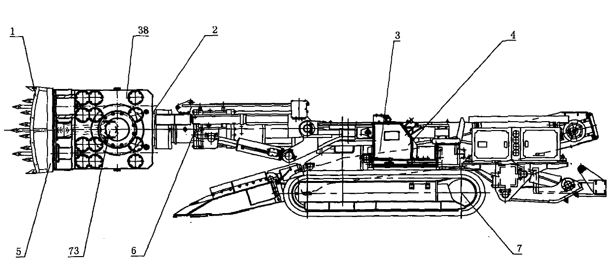
[0478] figure 1 , figure 2As shown, a rotary motion is transformed into a reciprocating impact motion device, including a fuselage 4, a walking part 7, a reciprocating impact part 5, etc., and the reciprocating impact part 5 includes an impact drive mechanism 2, a rocker arm 6, an impact head 1, etc., and the impact drive Mechanism 2 includes an impact power source 11, a transmission component, a crankshaft, etc., the impact power source 11 is arranged perpendicular to the rocker arm 6, the impact power source 11 is a motor, the motor includes a power output shaft 14, and the transmission component includes a gear transmission component, the gear Transmission part comprises power gear 13, transmission gear 12, and impact power source part 11 comprises power output shaft 14, and power gear 13 is installed on the power output shaft 14, and transmission gear 12 drives crankshaft, and transmission part comprises transmission shaft, and power output shaft 14 is perpendicular to T...

Embodiment 2

[0483] image 3 As shown, a rotary motion is converted into a reciprocating impact motion device. The rocker arm 6 includes a fixed seat 9, a movable arm 8, etc., the fixed seat 9 and the rocker arm 6 are separately arranged, and the impact drive mechanism 2 is arranged on the movable arm 8. The arm 8 is arranged on the fixed seat 9, and the fixed seat 9 is hinged with the movable arm 8, so that the telescopic movement of the impact drive mechanism 2 can be realized.

[0484] The fixed seat 9 can be integrated with the rocker arm 6, and then the fixed seat 9 is fixedly connected with the movable arm 8.

[0485] Others are with embodiment 1.

Embodiment 3

[0487] Figure 4 As shown, a rotary motion is converted into a reciprocating impact motion device. The rocker arm 6 includes a rotating device 15, a fixed seat 9, a movable arm 8, etc., the fixed seat 9 includes a fixed arm and / or a bracket, and the fixed seat 9 and the movable arm 8 are movable. Connecting, one end of the rotating device 15 is arranged on the fixed seat 9 , the other end of the rotating device 15 is connected with the movable arm 8 , and the rotating device 15 drives the movable arm 8 to rotate relative to the fixed seat 9 .

[0488] The rotating device 15 can be arranged on the movable arm 8 or on the fixed base 9 and the movable arm 8 .

[0489] Others are with embodiment 1.


PUM


Abstract

A method and device for converting rotary motion to reciprocating percussion motion. The device comprises a machine body (4), a travel portion (7), and a reciprocating percussion portion (5). The reciprocating percussion portion (5) comprises a percussion drive mechanism (2), a rocker arm (6), and a percussion head (1). The percussion drive mechanism (2) comprises a percussion power source member (11), a transmission component, and a crankshaft (10). The percussion power source member (11) comprises a motor, and the motor comprises a power output shaft (14). The transmission component comprises a power gear (13) and a transmission gear (12). The power gear (13) is mounted on the power output shaft (14). The transmission gear (12) drives the crankshaft (10). The transmission component comprises a transmission shaft. The power output shaft (14) is perpendicular to the rocker arm (6), and is parallel to the transmission shaft and the crankshaft (10) so that the transmission gear (12) drives the crankshaft (10) to convert rotary motion to reciprocating motion; or the power output shaft (14) is parallel to the rocker arm (6), the crankshaft (10) is driven to convert rotary motion to reciprocating motion after the power direction is changed by a power bevel gear and a transmission bevel gear. The crankshaft (10) drives the percussion head (1) to perform reciprocating percussion. The travel portion (7) drives the machine body to travel. The machine body (4) drives the reciprocating percussion portion (5) to move and work continuously. The device applies to the mining field or mechanical engineering field, and has advantages such as strong structural strength and a small amount of maintenance.

Description

technical field [0001] The invention belongs to the field of machinery, and is especially applicable to a method for converting rotary motion into reciprocating impact motion equipment in the field of mining or construction machinery and the equipment for converting rotary motion into reciprocating impact motion for implementing the method. Background technique [0002] The drive shaft of the existing drilling-milling-cutting type roadheader is arranged longitudinally along the rocker arm, so that the drilling-milling-cutting head is easy to cause damage to the transmission parts such as the spline shaft and the spline sleeve when the drilling-milling cutting head expands and rotates, and the motor or the deceleration After the machine is damaged, the rocker arm must be disassembled in many places for maintenance. The maintenance is difficult, labor-intensive, time-consuming, and difficult to assemble. In the maintenance and disassembly, it is easy to cause damage to undamage...

Claims


Application Information

Patent Timeline
Patent Type & Authority Applications(China)
IPC IPC(8): E21C27/30E21C27/28E21C31/02
CPCE21B1/02E21C27/12E21C27/28
Inventor 刘素华
Owner 刘素华
Why Eureka
Try Eureka