Space relative deformation measuring device for upper disc and lower disc of in-situ rock joint plane

A measuring device and relative deformation technology, which is applied in the direction of mechanical solid deformation measurement, etc., can solve problems such as deformation, inability to test relative deformation, and failure to solve spatial relativity, so as to achieve strong environmental adaptability, high reusability, and stable and reliable measurement results Effect

Inactive Publication Date: 2014-01-08
INST OF ROCK AND SOIL MECHANICS - CHINESE ACAD OF SCI
View PDF8 Cites 18 Cited by
  • Summary
  • Abstract
  • Description
  • Claims
  • Application Information

AI Technical Summary

Problems solved by technology

Chinese Patent Publication No. CN 200910023156.0 A, publication date 2009.12.16, the title of the invention is "a method for determining deformation parameters of rock mass with non-penetrating joints and fissures". This application focuses on the determination of deformation parameters of jointed rock mass, but does not involve rock joints Measuring technique of relative motion between upper and lower walls of facets
Chinese Patent Publication No. CN 201310104806.0 A, publication date 2013.06.26, the title of the invention is "A Method for Determining the Mechanical Parameters of Jointed Rock Mass", the application is to comprehensively determine the mechanical parameters of jointed rock mass through rock strength testing and with the help of GSI and H-B strength criteria , also failed to solve the problem of measuring the relative deformation of the face wall and foot wall of rock joints in situ
[0005] On the other hand, other indoor measurement methods involving the relative deformation of the upper wall and the lower wall of the structure only involve the relative plane of the joint surface along a certain artificially given shear direction. Deformation measurement or relative deformation measurement in the normal compression direction, or measurement of a given shear and normal relative deformation, but cannot be applied to the three-dimensional space free relative deformation measurement of the undisturbed joint surface between the upper wall and the lower wall on the engineering site
"Journal of Rock Mechanics and Engineering", No. 1, 2006, titled "Shear test research on rock joints undergoing different deformation histories", author Du Shouji et al. This research involves the joint surface wall and footwall in the process of specifying the shear direction The measurement of shear deformation, but it cannot test the three-way (X, Y, Z) relative deformation between the upper wall and the lower wall of the original joint in the project
Chinese Patent Publication No. CN 201110259826.6 A, publication date 2012.02.15, invention name "a jointed rock mass excavation transient unloading loosening simulation system", the application developed the measurement technology in the dynamic unloading process of jointed rock, but It also fails to solve the problem of spatial relative deformation measurement during the unloading deformation of the in-situ rock joint surface
[0006]In fact, the measurement results of the spatial relative deformation between the face wall and the foot wall of rock joints in situ in engineering can directly reflect the activity of the joint / fracture rock mass at that time, The safety early warning of large jointed rock mass slopes and the stability evaluation of underground tunnels in jointed rock mass are very important, but there is a lack of on-site monitoring technology and monitoring equipment in this regard.

Method used


Image

  • Space relative deformation measuring device for upper disc and lower disc of in-situ rock joint plane
  • Space relative deformation measuring device for upper disc and lower disc of in-situ rock joint plane
  • Space relative deformation measuring device for upper disc and lower disc of in-situ rock joint plane

Examples


Embodiment Construction

[0021] Attached below figure 1 , attached figure 2 , attached image 3 And attached Figure 4 , the present invention will be further described.

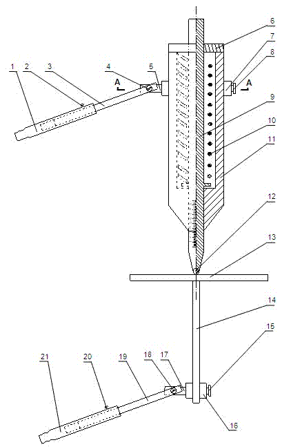
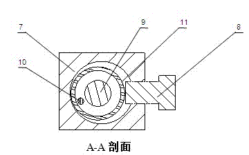
[0022]An in-situ space relative deformation measurement device for the upper wall and the lower wall of a rock joint is composed of an upper fixing mechanism, a lower fixing mechanism, a normal deformation measuring mechanism and a plane deformation measuring mechanism. The upper fixing mechanism consists of an upper fixing rod 1, an upper fixing Bolt 2, upper telescopic rod 3, upper fixed adjusting bolt 4, upper adjusting rod 5, upper connecting seat 7, upper locking bolt 8, the outer surface of the free end of the upper fixing rod 1 is hobbed, which can improve the installation of the device. The right end of the upper fixed rod 1 has a circular deep hole, and the left end of the upper telescopic rod 2 is movably placed in the round hole of the upper fixed rod 1 and fixed by the upper fixed bolt 3. In this way, the position ...


PUM


Abstract

The invention relates to a measuring device for monitoring space relative deformation caused by space relative movement of an upper disc and a lower disc of an in-situ rock joint plane in the wild. The measuring device consists of an upper fixing rod, an upper fixing screw bolt, an upper telescopic rod, an upper fixed regulating screw bolt, an upper regulating rod, an upper connecting seat, an upper locking screw bolt, a lower fixing rod, a lower fixing screw bolt, a lower telescopic rod, a lower fixed regulating screw bolt, a lower regulating rod, a lower connecting seat, a lower locking screw bolt, a normal displacement measuring rod, a telescopic spring, an outer sleeve, rolling balls, a sealing cap, a dial and a support rod through assembling connection. The device is respectively fixed with the upper disc rock and the lower disc rock of the joint plane through the upper fixing rod and the lower fixing rod, in addition, the normal displacement measurement is realized through the telescopic effect of the normal displacement measuring rod, and the plane deformation measurement is realized through the movement of the lower end part of a normal deformation measuring rod on the dial, so the measurement on the space relative deformation between the upper disc and the lower disc of the joint plane can be realized, and the measuring device has the advantage that the space relative deformation value of the upper disc and the lower disc of the rock joint plane is directly obtained.

Description

technical field [0001] The invention relates to a device for measuring the spatial relative deformation of the upper wall and the lower wall of an in-situ rock joint, and more particularly relates to a device for monitoring the spatial relative movement of the upper wall and the lower wall of the in-situ rock joint surface in the field to produce relative movement in three directions. Deformation measuring device. Background technique [0002] Due to the strong compression or tension structure in history, a large number of rock joints with different scales, different occurrences and different spacings are generally developed in the rock mass, such as the Ertan Hydropower Station in my country, the Xiaolangdi Project, and the high slope of the Three Gorges Permanent Ship Lock. A large number of outcropping of rock joint surfaces can be seen on the dam slopes and excavation surfaces of underground caverns of large-scale projects such as the underground powerhouse of Jinping II ...

Claims


Application Information

Patent Timeline
Patent Type & Authority Applications(China)
IPC IPC(8): G01B5/30
Inventor 江权李邵军冯夏庭崔洁樊义林胡连兴黄书岭
Owner INST OF ROCK AND SOIL MECHANICS - CHINESE ACAD OF SCI
Why Eureka
Try Eureka