
Automatic testing method and automatic testing device for parameters of microwave oscillator

A technology of automatic test device and microwave oscillator, which is applied in the direction of measuring device, instrument, measuring electronics, etc., can solve the problems of data reading and recording process errors, poor test consistency, and low test efficiency, so as to ensure accuracy and improve Accuracy and consistency, the effect of improving test efficiency

Active Publication Date: 2014-01-08
FIFTH ELECTRONICS RES INST OF MINIST OF IND & INFORMATION TECH
View PDF4 Cites 18 Cited by
  • Summary
  • Abstract
  • Description
  • Claims
  • Application Information

AI Technical Summary

Problems solved by technology

[0004] This method has the following disadvantages: 1. Manual reading and manual recording of data is prone to errors in the data reading and recording process; 2. Manual reading of data, because the test delay time is controlled by the tester, there is no standard, resulting in test consistency Poor, and different testers may get different test data; 3. The test efficiency is low by manual reading and manual recording

Method used


Image

  • Automatic testing method and automatic testing device for parameters of microwave oscillator
  • Automatic testing method and automatic testing device for parameters of microwave oscillator
  • Automatic testing method and automatic testing device for parameters of microwave oscillator

Examples


Embodiment Construction

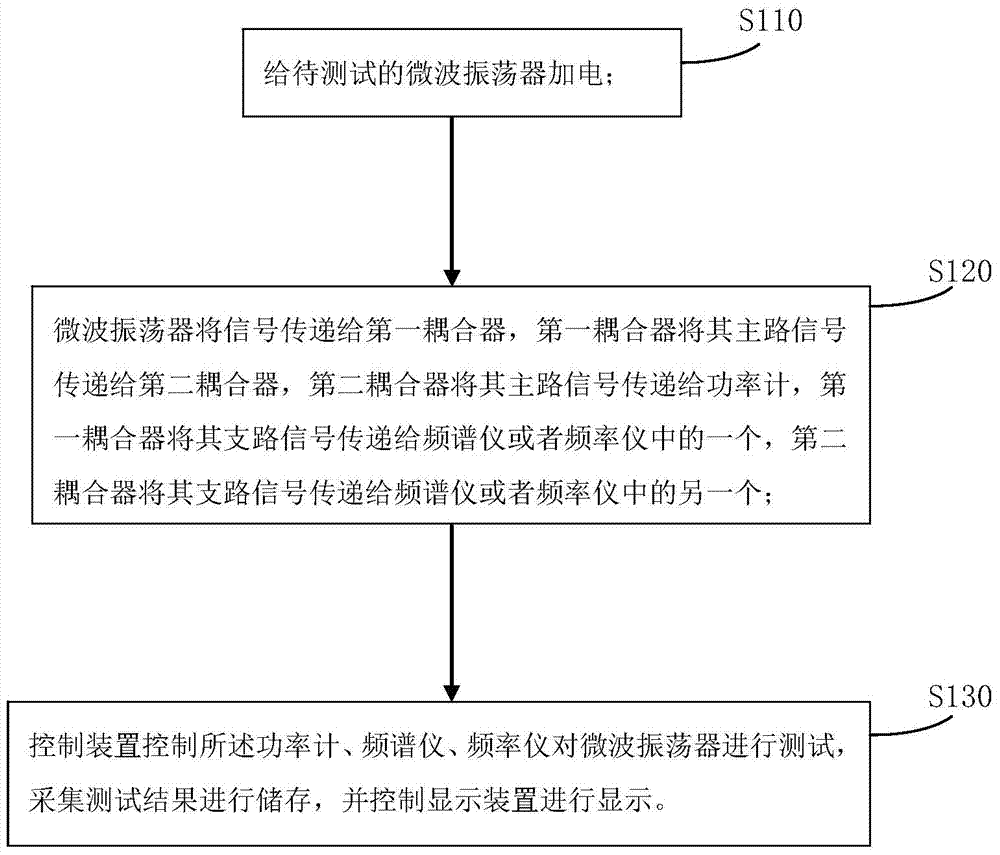
[0044] Such as figure 1 Shown, a kind of microwave oscillator parameter automatic test method, comprises the following steps:

[0045] S110: power on the microwave oscillator to be tested;

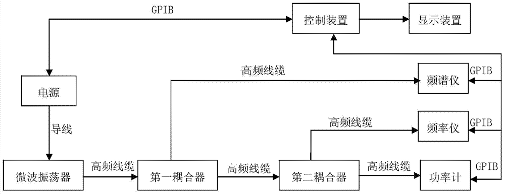
[0046] S120: The microwave oscillator transmits the signal to the first coupler, the first coupler transmits its main channel signal to the second coupler, the second coupler transmits its main channel signal to the power meter, and the first coupler transmits its main channel signal to the power meter. The branch signal is transmitted to one of the spectrum analyzer or the frequency analyzer, and the second coupler transmits its branch signal to the other of the spectrum analyzer or the frequency analyzer;

[0047] S130: The control device controls the power meter, spectrum analyzer, and frequency meter to test the microwave oscillator, collects and stores test results, and controls the display device to display.

[0048]The above-mentioned microwave oscillator parameter automatic testi...


PUM


Abstract

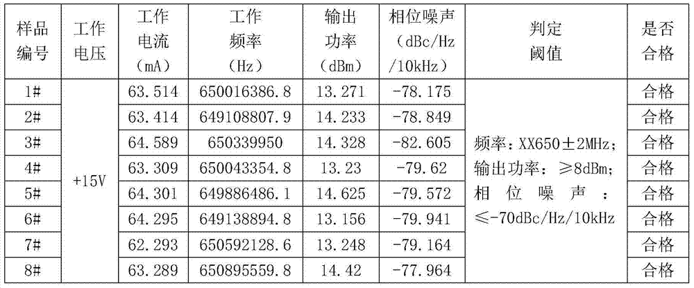
The invention discloses an automatic testing method for parameters of a microwave oscillator. The automatic testing method comprises the following steps of powering up the to-be-tested microwave oscillator; transmitting a signal to a first coupler by the microwave oscillator, transmitting a main signal of the first coupler to a second coupler by the first coupler, transmitting a main signal of the second coupler to a power meter by the second coupler, transmitting a branch signal of the first coupler to one of a frequency spectrograph and a frequency meter by the first coupler, and transmitting a branch signal of the second coupler to the other one of the frequency spectrograph and the frequency meter by the second coupler; controlling the power meter, the frequency spectrograph and the frequency meter by a control device to test the microwave oscillator, acquiring testing results and storing, and controlling a display device to display. According to the method, automatic testing of the working frequency, the output power and the phase noise of the microwave oscillator can be realized, and data does not need to be manually read and manually recorded, and therefore, the accuracy and the consistency of the testing results are improved, and the testing efficiency is improved. The invention also discloses an automatic testing device for the parameters of the microwave oscillator.

Description

technical field [0001] The invention relates to microwave oscillator parameter testing technology, in particular to a microwave oscillator parameter automatic testing method and device. Background technique [0002] Microwave frequency sources are the key to achieving high performance in electronic systems such as radar, communications, and electronic countermeasures. The realization of many modern microwave electronic equipment and system functions directly depends on the performance of microwave frequency sources used, and microwave oscillators are used as microwave frequency sources. Core components are therefore very important. Microwave oscillators are used to generate microwave signals. They are the basic microwave energy source for all microwave systems such as radar, communication, navigation or electronic warfare systems. Its quality directly affects the performance indicators of these systems and is one of the key components of various microwave systems. , is curr...

Claims


Application Information

Patent Timeline
Patent Type & Authority Applications(China)
IPC IPC(8): G01R31/00
Inventor 尧彬陈辉来萍肖庆中陈安定马建军
Owner FIFTH ELECTRONICS RES INST OF MINIST OF IND & INFORMATION TECH
Learn More