Non-contact pipeline defect detection device with GPS (Global Positioning System) positioning function and detection method

A GPS positioning, non-contact technology, applied in the field of non-contact pipeline defect detection devices, can solve the problems of low contact or distance detection, no positioning function, defects, etc., and achieves shielding magnetic field interference and good anti-interference performance. , the effect of high detection accuracy

Inactive Publication Date: 2014-01-08
HARBIN INST OF TECH
View PDF5 Cites 10 Cited by
  • Summary
  • Abstract
  • Description
  • Claims
  • Application Information

AI Technical Summary

Problems solved by technology

[0005] In order to solve the problem that the existing detection equipment can only perform detection with low contact or distance measurement and has no positioning function, the present invention further proposes a non-contact pipeline defect detection device and detection method with GPS positioning function

Method used


Image

  • Non-contact pipeline defect detection device with GPS (Global Positioning System) positioning function and detection method
  • Non-contact pipeline defect detection device with GPS (Global Positioning System) positioning function and detection method
  • Non-contact pipeline defect detection device with GPS (Global Positioning System) positioning function and detection method

Examples


specific Embodiment approach 1

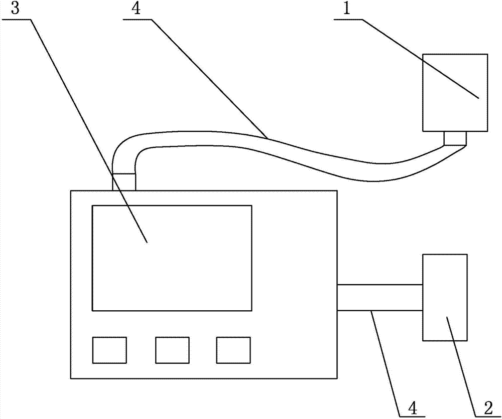
[0016] Specific implementation mode one: combine figure 1 Describe this embodiment, a non-contact pipeline defect detection device with GPS positioning function described in this embodiment includes a scanning mechanism 1, a GPS positioning system 2, a host 3 and two data lines 4, and the data transmission interface of the scanning mechanism 1 Connect with the communication interface of the host 3 through a data line 4, the communication interface of the GPS positioning system 2 is connected with the communication interface of the host 3 through a data line 4, the GPS positioning system 2 is composed of a signal passive receiving antenna and a data processing chip The signal passive receiving antenna is connected with the data processing chip, and the data processing chip is connected with the communication interface. Import the latitude and longitude data stored by the detection equipment into Google Earth, call Google Earth, and draw the detection path on its three-dimension...

specific Embodiment approach 2

[0018] Specific implementation mode two: combination figure 1 Describe this embodiment. The scanning mechanism 1 of a non-contact pipeline defect detection device with GPS positioning function described in this embodiment is composed of a magnetoresistive sensor, a filter circuit, and a data transmission interface. The magnetoresistive sensor is connected to the filter circuit, and the filter circuit The circuit is connected with the data transmission interface.

[0019] The magnetoresistive sensor in this embodiment selects a magnetoresistive sensor with a sensitivity in the micro-Gauss level, and uses the sensor position reset method and electromagnetic shielding method to design, avoiding electromagnetic waves and interference magnetic fields generated by electromagnetic equipment or other interference magnetic fields existing in the detection environment Effects on testing equipment. Other components and connections are the same as those in the first embodiment.

specific Embodiment approach 3

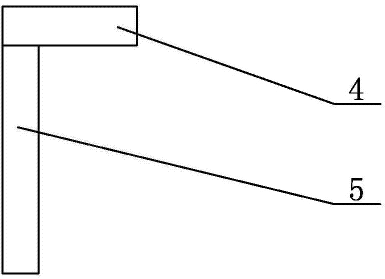
[0020] Specific implementation mode three: combination figure 2 To illustrate this embodiment, the magnetoresistive sensor of a non-contact pipeline defect detection device with GPS positioning function described in this embodiment is composed of a horizontal chip 5 and a vertical chip 6 perpendicular to each other.

[0021] The horizontal chip 5 in the present embodiment is the HMC1001 chip, and it is only sensitive to the magnetic field on one direction, and the vertical chip 6 is the HMC1002 chip, and it is sensitive to the magnetic field of two mutually perpendicular directions, and the horizontal chip 5 and the vertical chip 6 are combined Finally, the magnetic field in three directions can be detected simultaneously. Other components and connections are the same as those in the second embodiment.

[0022] Specific implementation mode three: combination figure 1 To illustrate this embodiment, the specific steps of a pipeline defect detection method using the device des...


PUM


Abstract

The invention relates to pipeline defect detection devices and methods and particularly relates to a non-contact pipeline defect detection device with a GPS (Global Positioning System) positioning function and a detection method. The detection device is used for solving the problems of the existing detection equipment that the existing detection equipment can only carry out contacted or low-distance-measurement detection and is not provided with a positioning function. The detection device comprises a scanning mechanism, a GPS, a host and two data wires, wherein the data transmission interface of the scanning mechanism is connected with the communication interface of the host through one data wire, the communication interface of the GPS is connected with the communication interface of the host through the other data wire, the GPS consists of a passive signal receiving antenna and a data processing chip, the passive signal receiving antenna is connected with the data processing chip, and the data processing chip is connected with the communication interface. The device and the method are applied to pipeline defect detection.

Description

technical field [0001] The invention relates to a pipeline defect detection device and detection method, in particular to a non-contact pipeline defect detection device and detection method with GPS positioning function. Background technique [0002] Ferromagnetic metals will produce metal magnetic memory effects under the action of corrosion, stretching, compression, twisting and cyclic loading. Metals will produce slip dislocation regions at stress concentration or corrosion locations, accompanied by their own leakage magnetic field. When there is a weak earth's magnetic field, a leakage magnetic field gradient will be formed on the surface of the stress concentration area of ​​the inspected object. The magnitude of the gradient can be obtained by using a special magnetic side instrument, and it can be used to determine whether a defect occurs. According to the mechanism of magnetic memory, the defect position of the ferromagnetic component will generate a large self-leak...

Claims


Application Information

Patent Timeline
Patent Type & Authority Applications(China)
IPC IPC(8): G01S19/42G01N27/82F17D5/02
CPCG01N27/82G01S19/14
Inventor 李隆球贺瑾瑜张广玉王杨杨刘伟民宋文平
Owner HARBIN INST OF TECH
Why Eureka
Try Eureka