
Liquid cooling insulation type radiator

An insulating heat sink technology, applied in the direction of electrical solid devices, semiconductor devices, semiconductor/solid device components, etc., can solve the problems of large cooling system, limited use range and complexity of high-voltage electric transmission devices, and achieve small size, Improve the heat dissipation effect and the effect of large heat dissipation area

Inactive Publication Date: 2014-01-08
张永亮
View PDF4 Cites 3 Cited by
  • Summary
  • Abstract
  • Description
  • Claims
  • Application Information

AI Technical Summary

Problems solved by technology

However, no matter which method makes the cooling system of the high-voltage electric drive relatively large and complicated, it limits the application range of the high-voltage electric drive

Method used


Image

  • Liquid cooling insulation type radiator
  • Liquid cooling insulation type radiator

Examples


Embodiment 1

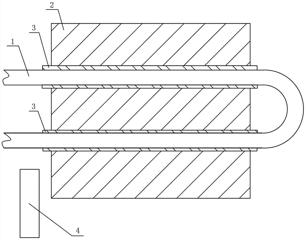
[0019] like figure 1 As shown, the liquid-cooled insulated heat sink of this embodiment includes: a heat-conducting substrate 2, and a substrate through-hole is provided inside the heat-conducting substrate 2, wherein the extending direction of the substrate through-hole is consistent with the extending direction of the heat-conducting substrate 2; Cooling pipe 1, the liquid cooling pipe 1 passes through the through hole of the substrate, the liquid cooling pipe 1 has a liquid inlet end and a liquid outlet end; a thermally conductive insulating material 3 is ringed between the hole wall of the substrate through hole and the liquid cooling pipe 1 to conduct heat The arrangement of the insulating material 3 enables the heat conduction substrate 2 and the liquid cooling pipe 1 to conduct heat and insulate each other.

[0020] In this embodiment, the liquid cooling pipe 1 is configured as a U-shaped pipe; its liquid inlet and outlet ends are located on the same side of the heat co...

Embodiment 2

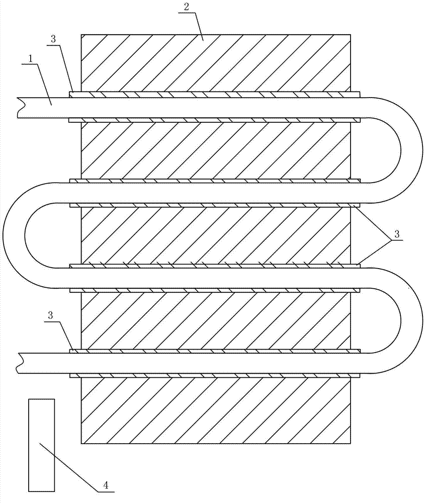
[0024] like figure 1 As shown, the second embodiment is basically the same as the first embodiment, except that the liquid cooling pipe 1 is a coil structure formed by connecting a plurality of U-shaped pipes in series; correspondingly, there are a plurality of substrate through-holes. The liquid cooling tube of the coil structure increases the heat transfer area, which can further improve the heat dissipation effect of the radiator.

[0025] In summary, using the liquid-cooled insulating radiator of the present invention, the heat generated by the power semiconductor device is transferred to the liquid cooling pipe through the heat-conducting substrate and the heat-conducting insulating material, and the heat is taken away by the medium flowing inside the liquid cooling pipe, realizing The purpose of heat dissipation and cooling of power semiconductor devices can meet the requirements of heat dissipation, insulation and small size at the same time, so that the high-voltage el...


PUM


Abstract

The invention discloses a liquid cooling insulation type radiator which comprises a thermal conductive substrate, substrate through holes which conform to the extending direction of the thermal conductive substrate are formed inside the thermal conductive substrate, a liquid cooling tube penetrates through the substrate through holes, and thermal conductive insulation materials are arranged between the hole walls of the substrate through holes and the liquid cooling tube so that the thermal conductive substrate and the liquid cooling tube can transfer heat and can also be mutually insulated. The liquid cooling insulation type radiator further comprises an insulation monitor used for detecting the insulation performance of the thermal conductive materials. By means of the liquid cooling insulation type radiator, heat produced by a power semiconductor device passes through the thermal conductive substrate and the thermal conductive insulation materials and is transmitted to the liquid cooling tube, media flowing in the liquid cooling tube take away the heat, the aim for radiating and cooling the power semiconductor device is achieved, the requirements for radiation, insulation and small size are met at the same time, and a high voltage electric drive device can meet requirements of some special environments.

Description

technical field [0001] The invention relates to the technical field of radiators, in particular to a liquid-cooled insulating radiator. Background technique [0002] At present, due to the limitation of the insulation level of power semiconductor devices in medium and high voltage electric transmission devices, the power semiconductor devices in use are generally completely insulated from the shell or grounding part of the electric transmission device. Two cooling methods are generally used for power semiconductor devices: one is that the power semiconductor devices and radiators are insulated from other components, and direct air cooling is used; the other is that power semiconductor devices and radiators are cooled by deionized water circulation. However, either way makes the cooling system of the high-voltage electric transmission relatively large and complicated, which limits the application range of the high-voltage electric transmission. Contents of the invention ...

Claims


Application Information

Patent Timeline
IPC IPC(8): H01L23/473H01L23/367H01L23/58
Inventor 张永亮
Owner 张永亮
Learn More