Tree-shaped antenna
An antenna and tree-shaped technology, applied in the field of miniaturized ultra-wideband antennas, can solve the problems of inability to achieve wide bandwidth angular scanning, unsuitable for airborne platform installation, large logarithmic period antenna unit size, etc. The effect of reducing floor space and lateral size reduction
- Summary
- Abstract
- Description
- Claims
- Application Information
AI Technical Summary
Problems solved by technology
Method used
Image
Examples
Embodiment 1
[0032] see Figure 4 , a preferred embodiment of the present invention is a first-order fractal log-periodic antenna. The antenna includes a first feeder rod 11, a second feeder rod 12 and six pairs of vibrators; the upper ends of the first feeder rod 11 and the second feeder rod 12 are connected to form a herringbone, and the gap between the two feeder rods is The angle 18 between the feed rods is 6 degrees; each pair of vibrators is one level, and the six pairs of vibrators increase step by step from top to bottom; the six pairs of vibrators are all first-order fractal vibrators, which are the first fractal vibrator 1 and the second fractal vibrator respectively. The vibrator 2, the third fractal vibrator 3, the fourth fractal vibrator 4, the fifth fractal vibrator 5 and the sixth fractal vibrator 6 are respectively symmetrically installed on two feeder rods; the structures of the six pairs of vibrators are the same, but the sizes are different. See the specific structure ...
Embodiment 2
[0037] see Figure 5 , another preferred embodiment of the present invention is a second-order fractal log-periodic antenna. The antenna includes a first feeder rod 11, a second feeder rod 12 and four pairs of second-order fractal oscillators, and each pair of second-order fractal oscillators in the four pairs of second-order fractal oscillators is the seventh fractal oscillator 7 and the eighth fractal oscillator respectively. Vibrator 8, ninth fractal vibrator 9, and tenth fractal vibrator 10; the upper ends of the two feed rods are connected to form a herringbone shape, and the angle 18 between the two feed rods is 6 degrees; each pair of two The first-order fractal oscillators are symmetrically installed on two feed rods; each pair of second-order fractal oscillators has the same structure, but different sizes, and the size increases gradually from top to bottom. See the specific structure image 3 , the second-order fractal oscillator includes three first-order fractal ...
Embodiment 3
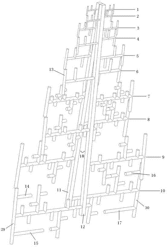
[0043] see figure 1 , another preferred embodiment of the present invention is a logarithmic periodic antenna composed of a first-order fractal oscillator and a second-order fractal oscillator. The antenna includes a first feeder rod 11, a second feeder rod 12, six pairs of first-order fractal oscillators and four pairs of second-order fractal oscillators, and one group of six pairs of first-order fractal oscillators is the first fractal oscillator 1, the second Fractal oscillator 2, third fractal oscillator 3, fourth fractal oscillator 4, fifth fractal oscillator 5 and sixth fractal oscillator 6, one of the four pairs of second-order fractal oscillators is the seventh fractal oscillator 7, the eighth fractal oscillator 8, The ninth fractal vibrator 9 and the tenth fractal vibrator 10; the upper ends of the two feed rods are connected to form a herringbone shape, and the included angle is 18 between the feed rods; each pair of fractal vibrator is symmetrically installed on th...
PUM
 Abstract
Description
Claims
Application Information
 - R&D
- Intellectual Property
- Life Sciences
- Materials
- Tech Scout
- Unparalleled Data Quality
- Higher Quality Content
- 60% Fewer Hallucinations
Browse by: Latest US Patents, China's latest patents, Technical Efficacy Thesaurus, Application Domain, Technology Topic, Popular Technical Reports.
© 2025 PatSnap. All rights reserved.Legal|Privacy policy|Modern Slavery Act Transparency Statement|Sitemap|About US| Contact US: help@patsnap.com


