Glass cleaning robot

A glass-cleaning robot and body technology, applied in vacuum cleaners, cleaning equipment, household appliances, etc., can solve the problems of easy dislocation, inconvenient use, and insecurity, and achieve the effects of strong controllability, simple structure and high sensitivity

Active Publication Date: 2016-06-08
ECOVACS ROBOTICS (SUZHOU ) CO LTD
View PDF5 Cites 0 Cited by
  • Summary
  • Abstract
  • Description
  • Claims
  • Application Information

AI Technical Summary

Problems solved by technology

Although this design can clean the front and back planes of the glass at the same time, it has relatively high requirements on the magnet and has restrictions on the working environment of the machine. If there is an obstacle on one side of the glass, the master and slave will easily misalign and cause the machine to fall
Moreover, this structure also has certain requirements on the thickness of the glass. When the thickness of the glass exceeds a certain range, the machine cannot be used.
At the same time, when using the machine, two-handed operation is required. At the same time, the main machine and the driven machine are placed on the front and back sides of the glass, which is not convenient to use, especially when working in a high-altitude environment, it is inconvenient and unsafe
In addition, the glass cleaning robots currently on the market consider the reason why the machine needs to return after welting. The ends of the machine are designed to be arc-shaped to facilitate the rotation and return of the body. The corners of the glass cannot be wiped, leaving dead corners, and the machine cannot fully play its role in cleaning the glass

Method used


Image

  • Glass cleaning robot
  • Glass cleaning robot
  • Glass cleaning robot

Examples


Embodiment Construction

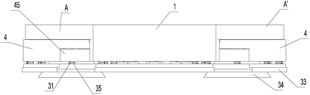
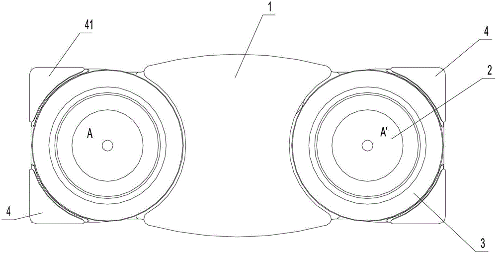
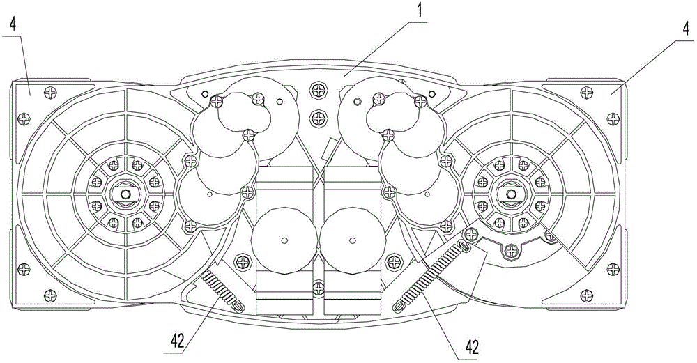
[0023] figure 1 It is a schematic diagram of the overall structure of the present invention; figure 2 for figure 1 bottom view of image 3 for figure 1 top view of Figure 4 It is a schematic diagram of the local structure of the present invention; Figure 5 for Figure 4 sectional view. combine Figure 1 to Figure 5 As shown, the present invention provides a glass-wiping robot, including a body 1 on which a control unit, a drive unit (not shown) and a first cleaning unit 2 are provided, and the glass-wiping robot also includes a rotatable A pair of adsorption turntables 3 at both ends of the bottom of the body 1, the drive unit is connected with the adsorption turntables 3 through a control unit, and the control unit controls the magnitude and direction of power output on the two adsorption turntables 3 respectively, and drives the pair of adsorption turntables 3 The adsorption turntable 3 rotates or is stationary around the vertical axis perpendicular to the glass s...


PUM


Abstract

A glass-wiping robot, comprising a body (1) on which a control unit, a drive unit, and a first cleaning unit (2) are arranged, and the glass-wiping robot also includes a pair of adsorption turntables (3) rotatably arranged at both ends of the bottom of the body , the drive unit is connected to the adsorption turntable through the control unit, the control unit respectively controls the magnitude and direction of power output on the two adsorption turntables, and drives the pair of adsorption turntables to rotate or stay still around the vertical axis perpendicular to the glass surface, Make a pair of adsorption turntables at both ends form a speed difference to realize the walking of the glass cleaning robot; wherein, a corner dust removal unit (4) is rotatably arranged between the body and the adsorption turntable, and the edge of the corner dust removal unit is at least partially protruding from the adsorption turntable The outer edge of the dust removal part is formed, and the shape of the outer edge of the dust removal part corresponds to the corner profile to be dust removed. The invention has the advantages of simple structure, flexible movement and strong controllability, and effectively completes dust removal and cleaning work on each corner.

Description

technical field [0001] The invention relates to a glass-wiping robot, which belongs to the technical field of small household electric appliances. Background technique [0002] Existing glass-cleaning robots usually wipe the front and back planes of the glass with a rag that is compressed by magnets that are attracted to each other, so as to achieve the effect of cleaning the glass. At present, the glass cleaning robots on the market use the mutual adsorption of the main machine and the driven machine, so that the machine is clamped on both sides of the glass, and the glass surface is cleaned with a rag sandwiched between the machine and the glass. Although this design can clean the front and back planes of the glass at the same time, it has relatively high requirements on the magnet and has restrictions on the working environment of the machine. If there is an obstacle on one side of the glass, the master and slave will easily misalign and cause the machine to fall . More...

Claims


Application Information

Patent Timeline
Patent Type & Authority Patents(China)
IPC IPC(8): A47L1/02
CPCA47L1/02A47L9/062
Inventor 冯勇兵
Owner ECOVACS ROBOTICS (SUZHOU ) CO LTD
Why Eureka
Try Eureka