Waste gas treatment device

A waste gas treatment device and waste gas treatment technology, which are applied in the separation of dispersed particles, chemical instruments and methods, and filtration of dispersed particles, etc., to achieve the effect of simple thinking, easy implementation and good application prospects.

Inactive Publication Date: 2014-01-15
江苏兆年智能科技有限公司
View PDF4 Cites 2 Cited by
  • Summary
  • Abstract
  • Description
  • Claims
  • Application Information

AI Technical Summary

Problems solved by technology

[0003] In order to overcome the problem of cleaning the waste gas processor in the prior art, it is necessary to suspend the work of the spray booth and stop the discharge of waste gas

Method used


Image

  • Waste gas treatment device

Examples


Embodiment Construction

[0013] The present invention will be further described below in conjunction with the accompanying drawings.

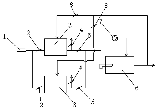
[0014] Such as figure 1 As shown, an exhaust gas treatment device includes several exhaust gas treatment branches, the number of exhaust gas treatment branches is between 2-4, preferably 2, and 2 branches can meet the gas treatment process. When the waste gas processor of one road is shut down for cleaning, the work of the other branch will not be affected. Each waste gas treatment branch shares a waste gas input port 1, and each waste gas treatment branch includes a first manual butterfly valve 2 connected to the waste gas input port 1. , the exhaust gas processor 3 and the second movable butterfly valve 5, the first manual butterfly valve 2 communicates with the input end of the exhaust gas processor 3 through a pipeline, and the heat energy output end of the exhaust gas combustion chamber 6 is respectively connected with each exhaust gas through the third movable bu...


PUM


Abstract

The invention discloses a waste gas treatment device. The waste gas treatment device comprises a plurality of waste gas treatment branches, wherein all the waste gas treatment branches share a waste gas input port; each waste gas treatment branch comprises a first manual butterfly valve, a waste gas treater and a second manual butterfly valve which are communicated with the waste gas input port; the first manual butterfly valves are communicated with the input ends of the waste gas treaters through pipelines; an exhaust valve is arranged at the output end of each waste gas treater; the output end of the waste gas treater of each waste gas branch is also communicated with the input end of a waste gas combustion chamber through the second manual butterfly valve; the thermal output end of the waste gas combustion chamber is connected with the waste gas treater of each waste gas treatment branch. According to the waste gas treatment device, when the waste gas treater of one branch is in operation, the waste gas treaters of the other branches perform high-temperature desorption through thermal energy output by the thermal output end of the waste gas combustion chamber. The continuous operation of the waste gas treatment device is realized, the thinking is simple, and the waste gas treatment device is easy to realize and has a good application prospect.

Description

technical field [0001] The invention relates to a waste gas treatment device, which belongs to the technical field of coating equipment. Background technique [0002] The painting room is to spray the filter painting objects in a relatively sealed room. During the painting process, the painting room will generate a large amount of exhaust gas, which contains a large number of paint particles. In recent years, with the continuous enhancement of people's awareness of environmental protection, The requirements for waste gas treatment are getting higher and higher. In the traditional waste gas treatment process of painting booths, the waste gas passes through a waste gas processor. The waste gas processor can absorb paint particles in the waste gas. After a period of use, the waste gas processor needs to be heated and desorbed. , The paint particles will leave the exhaust gas processor at high temperature, so as to remove the paint particles on the exhaust gas processor and achi...

Claims


Application Information

Patent Timeline
IPC IPC(8): B01D46/00
Inventor 杜勇何群伟
Owner 江苏兆年智能科技有限公司
Why Eureka
Try Eureka