

Full-automatic pipe end argon arc welding machine
A argon arc welding machine, fully automatic technology, used in arc welding equipment, welding equipment, welding equipment and other directions, can solve the problems of difficult welding and detachment, and achieve the effect of convenient and quick installation and positioning
- Summary
- Abstract
- Description
- Claims
- Application Information
AI Technical Summary
Problems solved by technology
Method used
Image

Examples
Embodiment 1
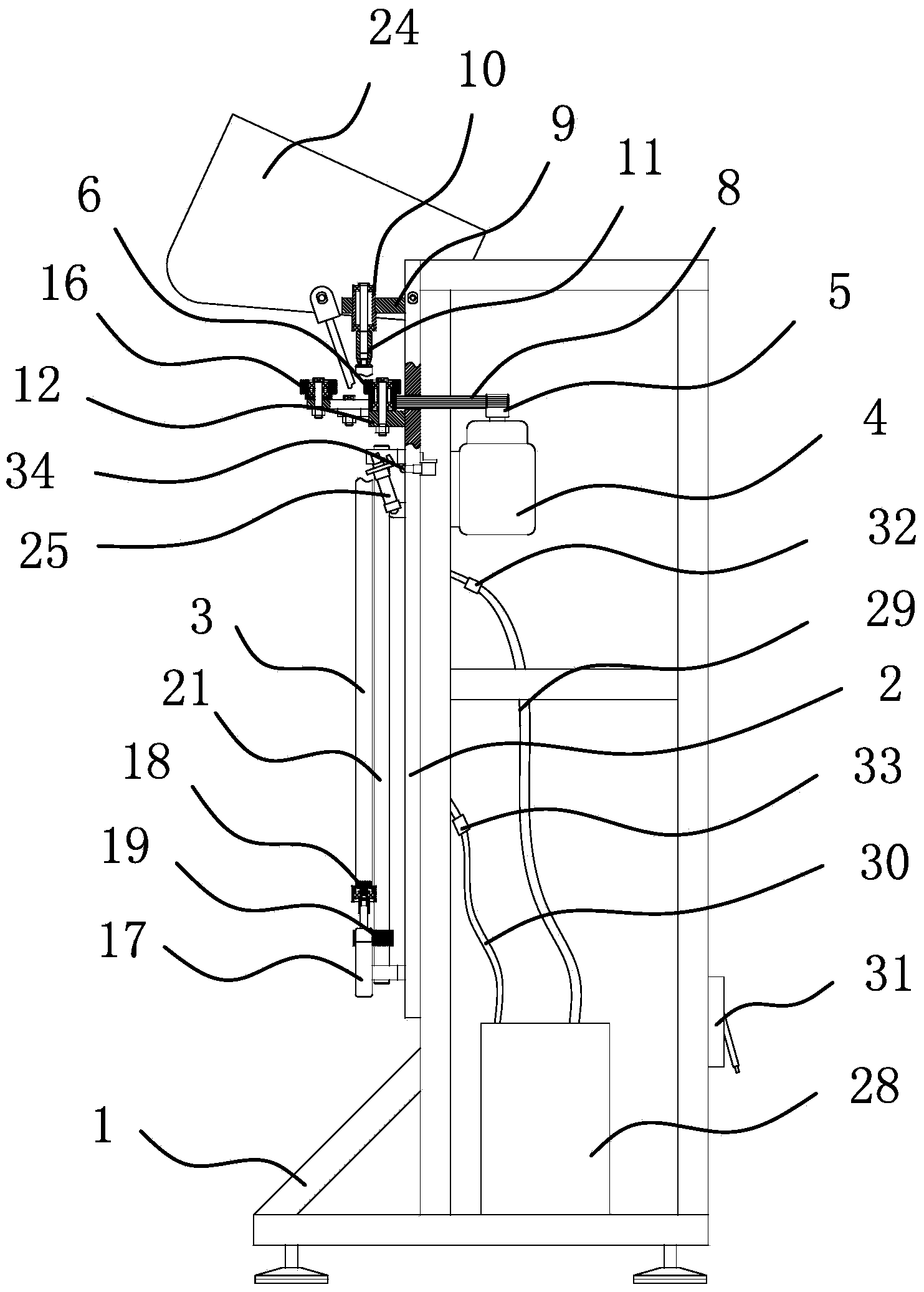
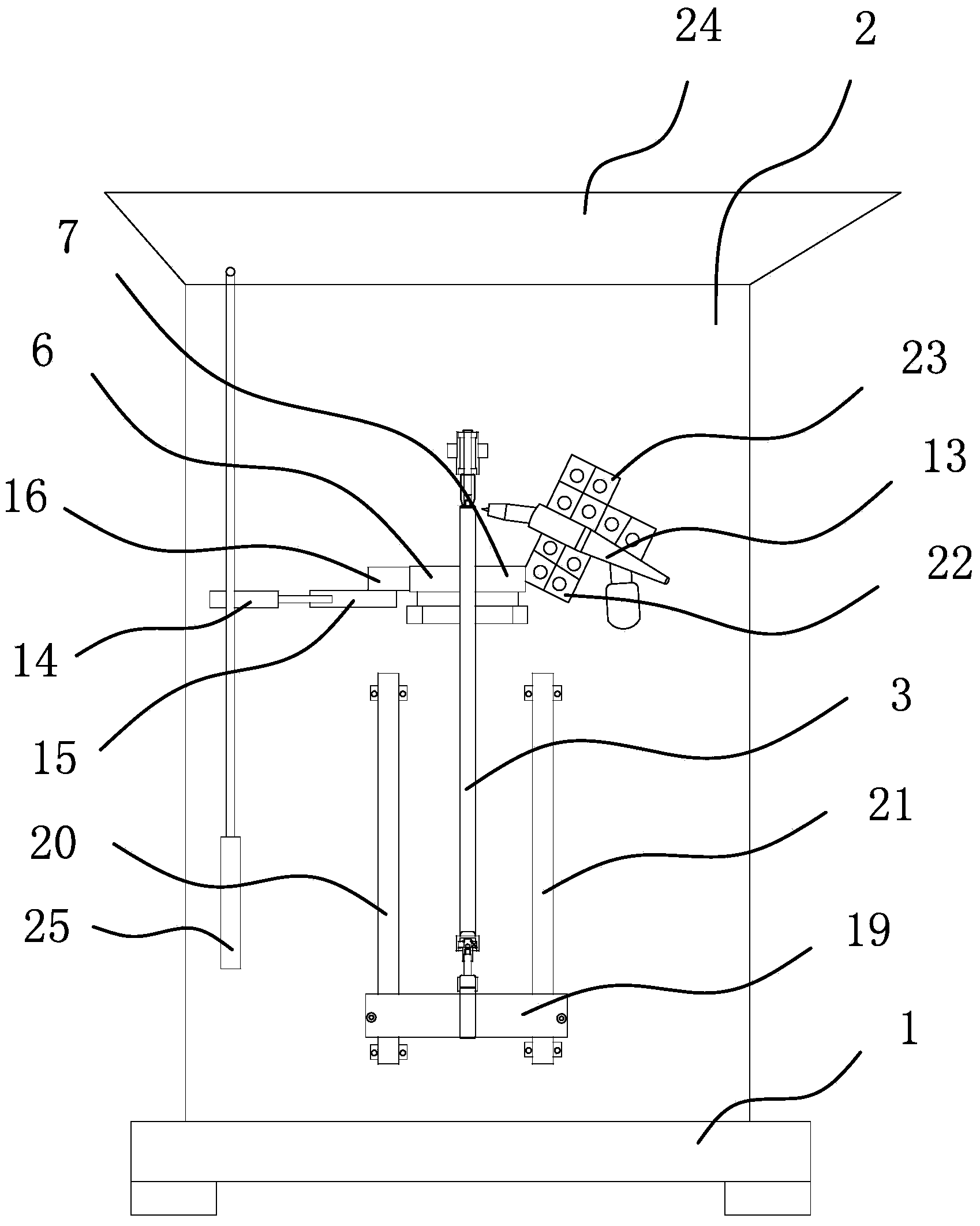
[0036] like figure 1 and 2 As shown, a fully automatic pipe end argon arc welding machine includes a frame 1, on which a mounting plate 2 is vertically fixed by screws, and a steel pipe 3 to be welded is vertically arranged on the mounting plate 2, the steel pipe 3 A pipe cap to be welded is installed on the upper end of the steel pipe, and one side of the mounting plate 2 is provided with an upper positioning structure and a lower positioning structure that can rotate the steel pipe 3 in the circumferential direction and position it axially, and the upper positioning structure is directly above the lower positioning structure. Between the upper positioning structure and the lower positioning structure, there is a rotating mechanism that can make the steel pipe 3 rotate circumferentially. The side of the mounting plate 2 is fixed with a welding torch 13 through a fixed structure. The muzzle of the welding torch 13 faces the upper end of the steel pipe 3, and the mounting plate...
Embodiment 2
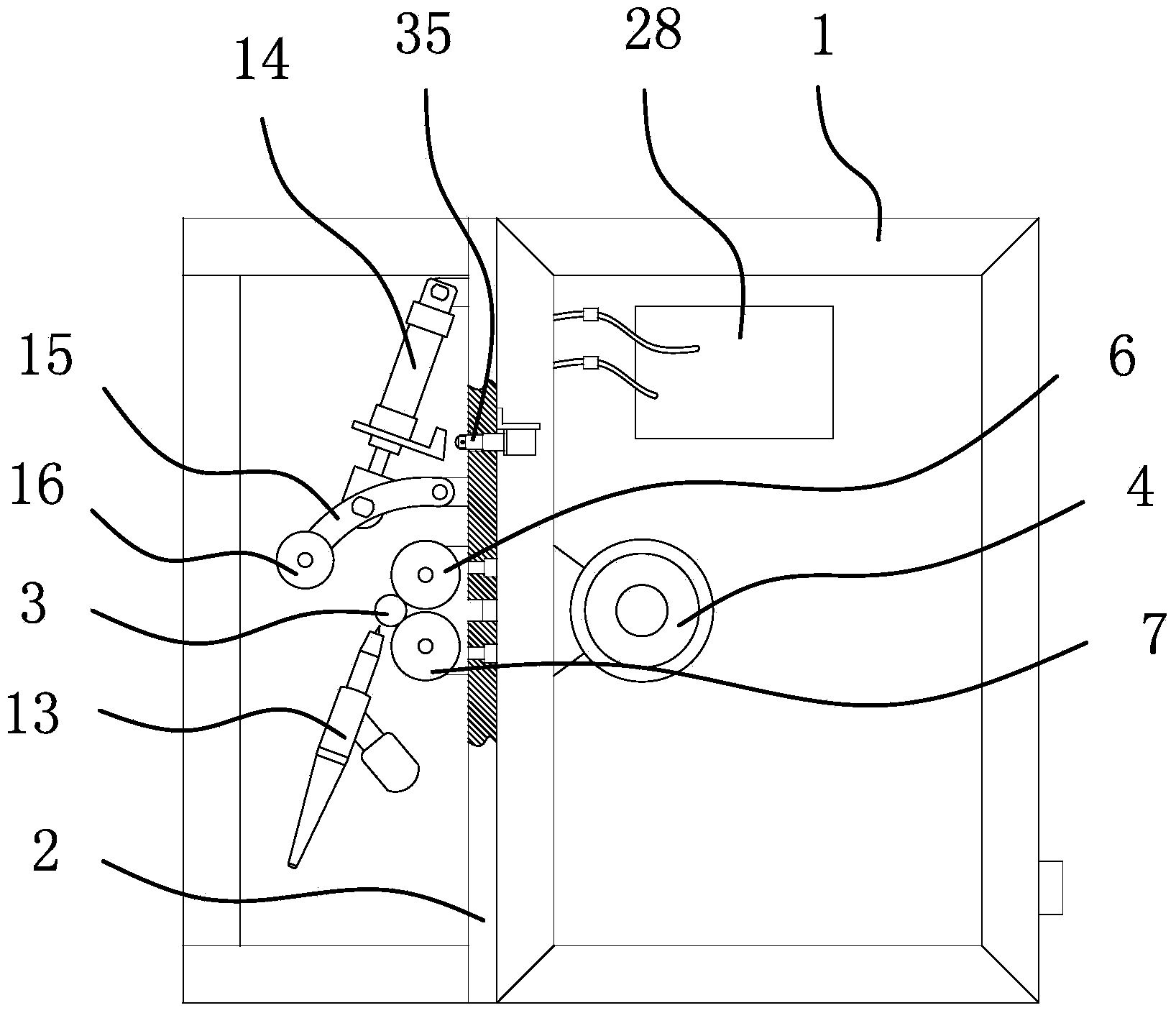
[0056]The structure and principle of this embodiment are basically the same as that of the first embodiment, the difference is that in the first embodiment, the pressing and holding mechanism includes a pressing wheel 16, a cylinder one 14 and a pressure rod 15; and in the second embodiment , the pressing and holding mechanism includes a pressing wheel 16, a push rod motor and a connecting rod. All on the same plane with the driven wheel 7, the other end of the connecting rod is hinged on the mounting plate 2, the push rod of the push rod motor is hinged on the middle part of the connecting rod, and the push rod motor is hinged on the mounting plate 2. In this embodiment, the holding mechanism always presses the steel pipe 3 on the driving wheel 6 and the driven wheel 7 in this way: the push rod of the push rod motor stretches out, and the connecting rod is close to the driving wheel 6 and the driven wheel 7 , the pressing wheel 16 moves toward the driving wheel 6 and the driv...
PUM
 Abstract
Description
Claims
Application Information