Rotary drilling rig

A technology for rotary drilling rigs and drill pipes, applied in the field of rotary drilling rigs, which can solve the problems of large friction, large size of rotary drilling rigs, and large output power of drawworks, etc., to achieve outstanding substantive features, reduce equipment costs, and reduce overall machine costs. The effect of energy consumption

Active Publication Date: 2014-01-15
覃炳德
View PDF7 Cites 6 Cited by
  • Summary
  • Abstract
  • Description
  • Claims
  • Application Information

AI Technical Summary

Problems solved by technology

Therefore, there are many defects in the traditional digging rig: 1. The self-weight of the drill bit is insufficient, and if it encounters hard soil, the force of downward pressure is insufficient; The frictional force is large, so that the power consumption of the whole machine is large; 3. The power head is heavy, and the drill pipe is subjected to a large force through direct drive and pressurization, so the output power of

Method used


Image

  • Rotary drilling rig
  • Rotary drilling rig
  • Rotary drilling rig

Examples


Embodiment 1

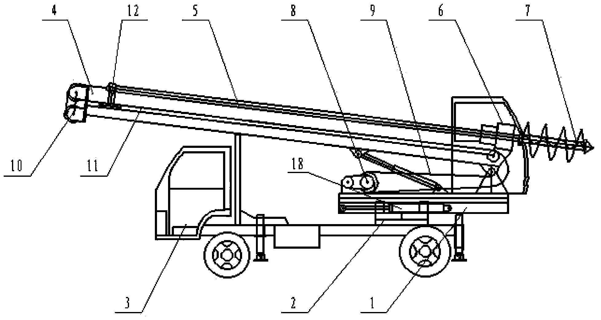
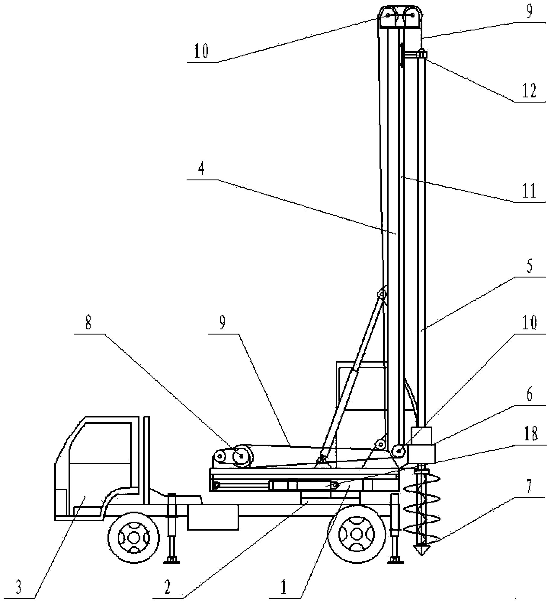
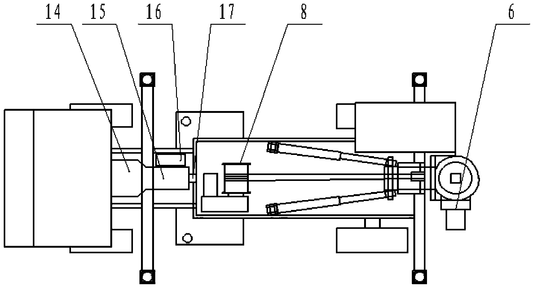
[0033] Such as Figure 1-Figure 4 As shown, a rotary drilling rig includes a driving device composed of an engine 14, a gearbox 15, a power take-off 16 and a two-stage hydraulic oil pump 17. The rotary drilling rig also includes a workbench 1, a column 4, a drill rod 5, a rotating Power head 6, drill bit 7, winch 8, wire rope 9 and pulley 10, column 4 and winch 8 are installed on the workbench 1, and workbench 1 is installed on the tracked vehicle by rotary disc 2. A steel wire rope 9 is wound on the winch 8, a sports car track 11 is arranged on the outside of the column 4, a drill pipe sports car 12 is installed on the sports car track 11, and the two ends of the drill pipe sports car 12 are fixedly connected with the steel wire rope 9 respectively. The wire rope 9 is connected to the drawworks 8 after the pulley 10 at the lower end of the column 4 changes direction respectively, and the drill rod sports car 12 moves up and down along the sports car track 11 under the drive o...

Embodiment 2

[0038] Such as Figure 5-Figure 7 As shown, the difference from the embodiment is that the workbench 1 is installed on the wheeled vehicle through the rotary disc 2, and the wheeled vehicle is a three-wheel drive axle structure, that is, it is driven by the front steering drive axle, the middle bridge and the rear axle. The movement of the workbench 1 makes the rotary drilling rig easy to drive, flexible and has good off-road performance. After the steel wire rope 9 changes direction through the pulley 10 at the lower end of the column 4, it is connected to the winch 8 through a set of pulley blocks, which reduces the power output requirements of the driving device and reduces energy consumption and cost. Drilling rod 5 is square column type, and the middle of rotary power head 6 is provided with the corresponding drilling rod hole that is square with the cross section of drilling rod 6, and drilling rod 5 penetrates in the drilling rod hole. The drill pipe 5 is provided with...


PUM


Abstract

The invention discloses a rotary drilling rig. The rotary drilling rig comprises a driving device, a workbench, a stand column, a drill pipe, a rotary power head, a drill bit, a winch, steel wire ropes and a pulley. The stand column and the winch are installed on the workbench, the steel wire ropes wind the winch, the outer side of the stand column is provided with a sports car track which is provided with a drill pipe sports car, the two ends of the drill pipe sports car are fixedly connected with the steel wire ropes respectively, the directions of the steel wire ropes at the two ends are changed through the pulley at the lower end of the stand column so that the steel wire ropes can be connected with the winch, and the steel wire ropes are driven by the winch to move up and down along the sports car track. The drill pipe is fixedly installed on the drill pipe sports car. Due to the fact that the stand column is provided with the sports car track and the drill pipe sports car, and direction changing is carried out through the pulley at the lower end of the stand column, a lever structure is formed, the weight of the whole car can be born by the drill pipe sports car with the pulley as a panel point, enough downwards pressure is given to the drill pipe and the drill bit through the drill pipe sports car, and the rotary drilling rig can fast and efficiently drill a hole in hard soil.

Description

technical field [0001] The invention relates to a piling machine, in particular to a rotary drilling machine. Background technique [0002] Rotary drilling rig, also known as "rotary bucket drilling rig", Astley drilling rig, etc., is a large-diameter deep hole forming equipment. Because the "rotary bucket" or "rotary bucket" is used to fetch soil and the square or round telescopic drill rod with sword is used to increase the drilling depth, it is called "rotary drilling rig" or "rotary bucket drilling rig". ". At present, there are two most common rotary drilling rigs on the construction site: one is the attachment type modified by crawler cranes, and the other is the imported and imitated excavator chassis modified through the trapezoidal linkage mechanism and hydraulic cylinder completely according to the foreign structure. The full hydraulic type that works together to adjust the verticality of the drill pipe. In recent years, the full-hydraulic type has developed rap...

Claims


Application Information

Patent Timeline
IPC IPC(8): E21B7/02
Inventor 覃炳德
Owner 覃炳德
Why Eureka
Try Eureka