Electromagnetic solenoid device for a starter

A technology of electromagnetic solenoids and solenoids, which is applied in the direction of engine motor starting, mechanical equipment, electromagnetic relays, etc., and can solve the problem of increasing the operating voltage of the solenoid SL1

Active Publication Date: 2014-01-15
DENSO CORP
View PDF7 Cites 3 Cited by
  • Summary
  • Abstract
  • Description
  • Claims
  • Application Information

AI Technical Summary

Problems solved by technology

This can lead to an increase in the operating voltage of solenoid SL1

Method used


Image

  • Electromagnetic solenoid device for a starter
  • Electromagnetic solenoid device for a starter
  • Electromagnetic solenoid device for a starter

Examples


Embodiment Construction

[0026] Exemplary embodiments of the present invention will now be described in detail below with reference to the accompanying drawings.

[0027] (First Exemplary Embodiment)

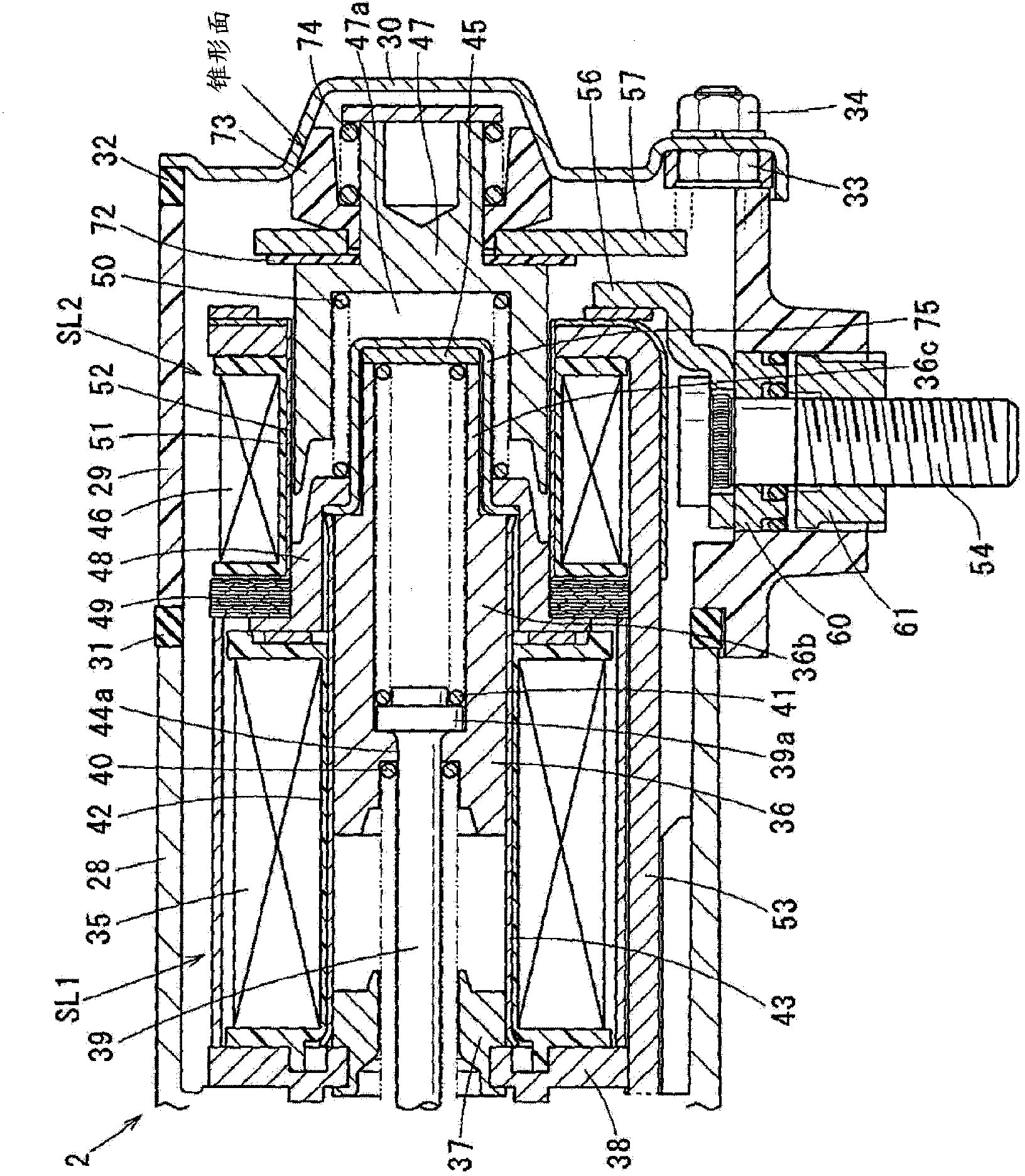
[0028] refer to Figure 1 to Figure 5 A first exemplary embodiment is described. In the present embodiment, an electromagnetic solenoid device 2 constituting an in-line solenoid type is employed as a deceleration type starter (hereinafter referred to as "starter 1").

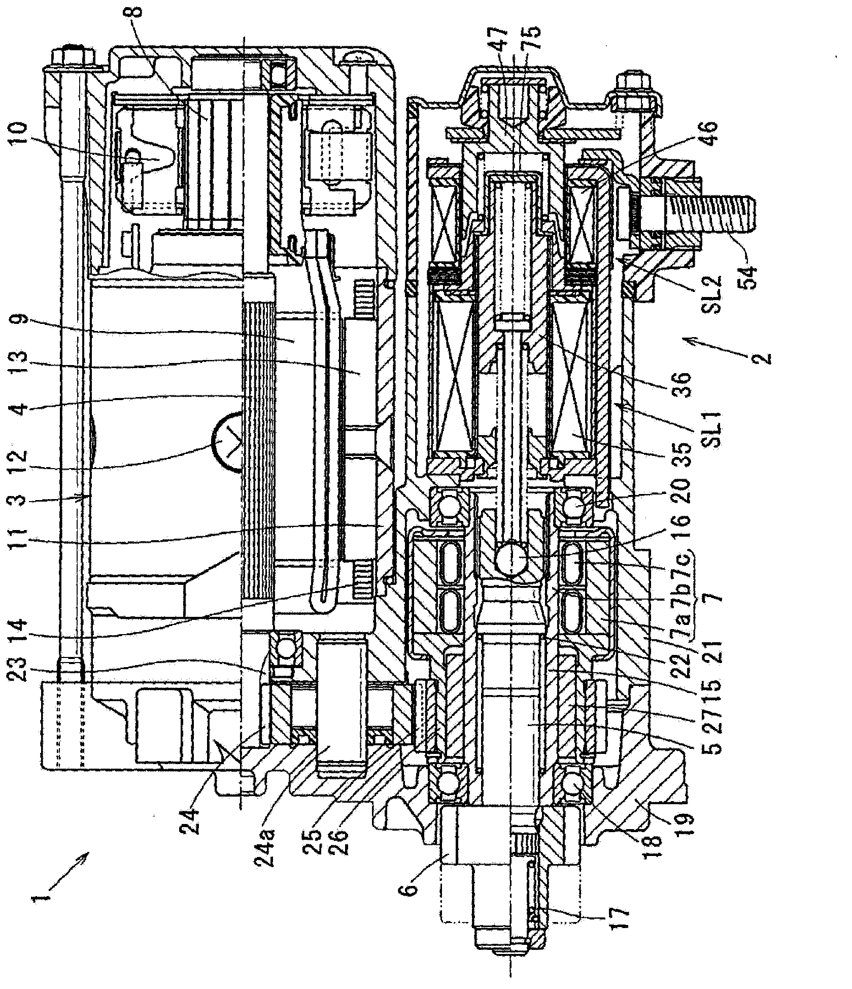
[0029] like image 3 As shown, the starter 1 includes, in addition to the electromagnetic solenoid device 2 , a motor 3 , a pinion 6 , a reduction gear unit and a clutch 7 . Motor 3 generates torque. The pinion shaft 5 is arranged parallel to the armature shaft 4 of the motor 3 . The pinion gear 6 is fixed to the outer periphery of the pinion shaft 5 so as to rotate together with the pinion shaft 5 . The speed reducer reduces the rotational speed of the motor 3 and increases the torque generated in the motor 3 . The clutch 7 transm...


PUM


Abstract

An electromagnetic solenoid device (2) for a starter motor includes a first solenoid (SL1) and a second solenoid (SL2). The first solenoid (SL1) includes a first coil (35) which is energized to form a first electromagnet, and a first plunger (36) is attracted by the first electromagnet to move in an inner periphery of the first coil (35) axially. The second solenoid (SL2) includes a second coil (46) which is energized to form a second electromagnet and a second plunger (47) which is attracted by the said second electromagnet to move in an inner periphery of the second coil (46) axially. The first solenoid (SL1) and the second solenoid (SL2) are held in a common switch frame. One movement direction of the first solenoid (SL1) which moves due to the attraction of the first electromagnet and a moving direction of the second solenoid (SL2) which moves due to the attraction of the second electromagnet are set to the same direction. A non-magnetic partition wall portion (75) is located between the first solenoid (SL1) and the second solenoid (SL2) .

Description

technical field [0001] The present invention relates to an electromagnetic solenoid device for a starter comprising a first solenoid for displacing a pinion towards the ring gear side of the engine and for opening or closing a power supply provided at The second solenoid of the main contact in the circuit, and in the electromagnetic wiring device, the first solenoid and the second solenoid are located in series in a common switch frame. Background technique [0002] In recent years, vehicles using an idle stop system (hereinafter referred to as "ISS") have become increasingly popular in order to improve fuel efficiency and limit carbon dioxide emissions. [0003] This ISS is configured to automatically stop the engine by cutting off the fuel supplied to the engine when the vehicle is temporarily stopped due to a stop signal at an intersection, or due to traffic jams and then when operated with the user for starting the vehicle A system that restarts an engine by automatical...

Claims


Application Information

Patent Timeline
IPC IPC(8): F02N11/08
CPCF02N11/087F02N15/06F02N2011/0892H01H50/10H01H51/065H01H51/20
Inventor 稻垣登久长谷川洋一名和幸男
Owner DENSO CORP
Why Eureka
Try Eureka