
Two-phase flow integrated quartz resistance furnace

A resistance furnace and phase flow technology, applied in the direction of silicon oxide, silicon dioxide, etc., can solve the problems of rising cable temperature, humid working environment, increasing contact resistance, etc., to reduce resistance loss, increase operating voltage, and reduce contact The effect of resistance

Active Publication Date: 2013-06-19
连云港富泰新材料科技有限公司
View PDF5 Cites 0 Cited by
  • Summary
  • Abstract
  • Description
  • Claims
  • Application Information

AI Technical Summary

Problems solved by technology

Because the power consumption of graphite electrodes (taking a 2-ton electric furnace as an example) is generally about 8000A, the cross-sectional area of ​​the cable in front of the furnace must reach 6000mm 2 As mentioned above, the weight of this high-current cable is estimated to exceed 50 kg per meter. Calculated with a 3-meter-long dry-type feeder cable, its weight is as high as 150 kg, and each pole of the electric furnace needs to be equipped with one. Such a 300-kg weight The cable must also rotate 180 degrees continuously with the heating furnace body, so cross-winding, wear, and leakage often occur; in addition, the working environment of the electric furnace is humid, high temperature, and dusty, which will inevitably greatly increase the contact of the cable and cause corrosion. The contact resistance increases, causing the temperature of the cable to rise. As a result of this vicious circle, a large amount of loss and waste of electric energy is caused.

Method used


Image

  • Two-phase flow integrated quartz resistance furnace
  • Two-phase flow integrated quartz resistance furnace
  • Two-phase flow integrated quartz resistance furnace

Examples


Embodiment Construction

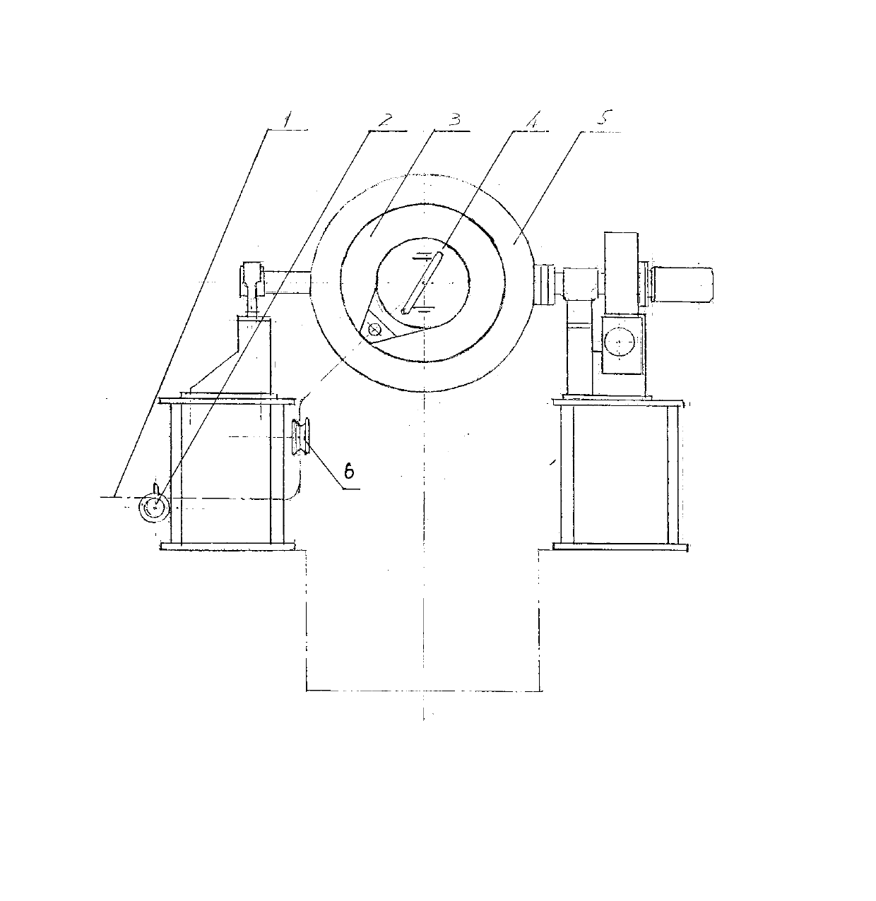
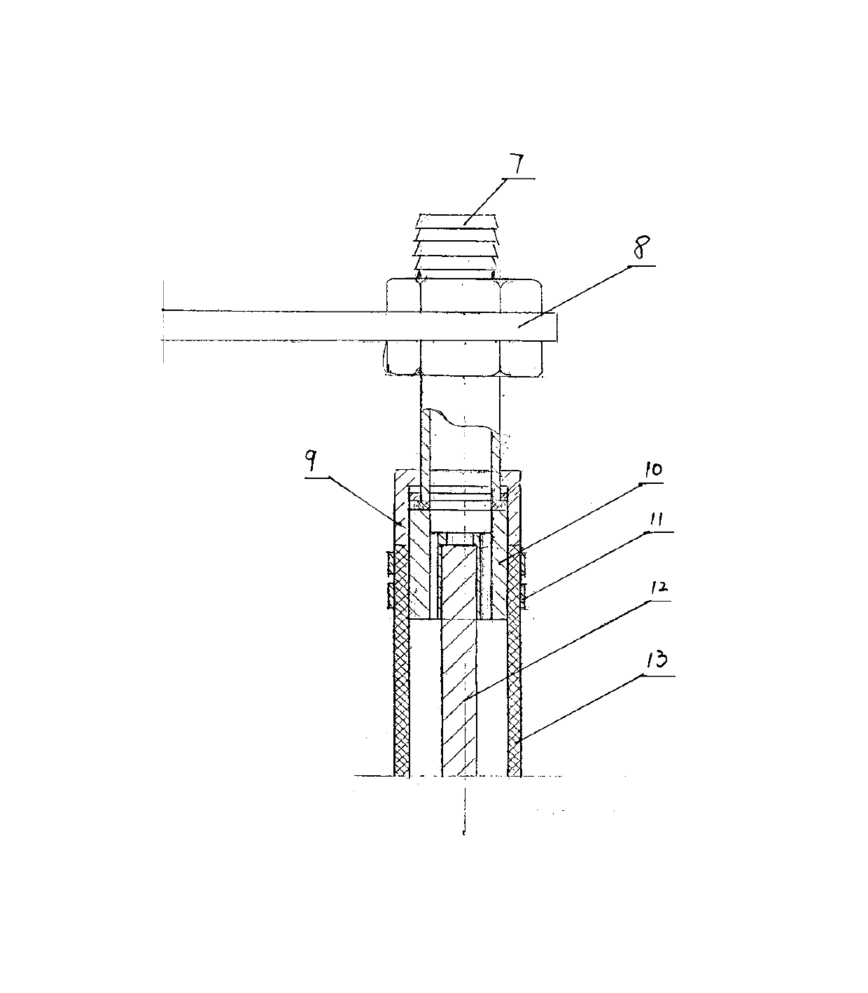
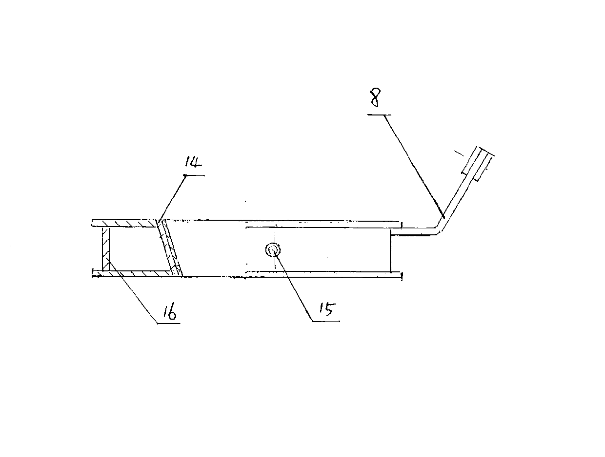
[0013] A two-phase flow integrated quartz resistance furnace, including a circular metal cylinder 5 mounted on a rotating shaft and capable of rotating 180 degrees, a graphite electrode is longitudinally arranged in the cylinder 5, and the two ends of the graphite electrode pass through the graphite electrode. The electrode sleeve 14 is connected with the composite electrode 8 arranged at both ends of the cylinder, the composite electrode 8 is connected with the low-voltage side of the transformer in front of the furnace through the cable 1, and the furnace cover cooling water drum 3 is arranged around the composite electrode 8, and the graphite electrode sleeve 14 is surrounded by a water-cooling jacket 4, the water-cooling jacket 4 includes an inner ring and an outer ring 16, the inner ring is composed of a graphite electrode sleeve 14, the composite electrode 8 made of copper-iron composite material is fixed to the outer ring 16, and the cable 1 is water-cooled Cables, water...


PUM

PropertyMeasurementUnit
areaaaaaaaaaaa

Abstract

The invention discloses a two-phase flow integrated quartz resistance furnace, which comprises a round metal cylinder body which is arranged on a rotating shaft and can rotate 180 degrees, an graphite electrode is longitudinally arranged in the round metal cylinder body, the two ends of the graphite electrode are connected with composite electrodes arranged at the two ends of the round metal cylinder body through graphite electrode sleeves, the composite electrodes are connected with a low voltage side of a furnace front transformer through cables, the peripheries of the composite electrodes are provided with furnace cover cooling water drums, the periphery of the graphite electrode is provided with water cooled jackets, the composite electrodes and the outer rings of the water cooled jackets are fixed, the cables are water cooled cables, the water cooled cables comprise copper core wires, rubber steam hoses are coated outside the copper core wires, cooling water channels are arrangedbetween the copper core wires and the rubber steam hoses, transition joints are arranged between the water cooled cables and the composite electrodes, and two-phase flow conduits of the transition joints are connected with the water cooled jackets. The two-phase flow integrated quartz resistance furnace reduces areas of the cables by more than 20 times, greatly reduces contact resistance between the electrodes at the two ends, reduces turning weight of a furnace body, greatly reduces operating accidents of equipment, and increases operating efficiency.

Description

technical field [0001] The invention relates to a quartz production and processing technology, in particular to a two-phase flow integrated quartz resistance furnace. Background technique [0002] Silica (SiO2) is called quartz in petrology. Quartz ore has unique physical and chemical properties after being smelted in an electric furnace, such as high temperature resistance, corrosion resistance, acid resistance, small thermal expansion coefficient, high insulation, stable and excellent chemical properties. optical properties and piezoelectric effect. In addition to a large number of applications of quartz in the field of life, people have also developed a large number of high-tech products, making great contributions to the global microelectronics industry, photovoltaic industry, military industry and other high-tech industries. According to statistics, the number of quartz resistance furnaces equipped in my country alone has reached more than 1,000, the annual power cons...

Claims


Application Information

Patent Timeline
Patent Type & Authority Patents(China)
IPC IPC(8): C01B33/12
Inventor 邱富仁
Owner 连云港富泰新材料科技有限公司
Learn More