Method for manufacturing water-cooled locomotive cylinder

A water-cooled, cylinder technology, applied in the direction of cylinders, cylinder heads, mechanical equipment, etc., can solve the problems of high consumables, increase costs, and affect efficiency

Inactive Publication Date: 2014-01-22
COLIS INDAL
View PDF7 Cites 0 Cited by
  • Summary
  • Abstract
  • Description
  • Claims
  • Application Information

AI Technical Summary

Problems solved by technology

[0004] And when above-mentioned cylinder body is made, as Figure 9 As shown, the cylinder body 3 is molded by a mold, because the water-cooled cylinder has a space for cooling water to flow through the middle flow, therefore, in the molding process, it is necessary to mold a cylinder with cooling water through the production of sand cores. space and channel, so that after the cylinder body 3 is made, there is a circulation space 33 between the piston wall 31 and the outer wall 32, and the upper and lower sides of the circulation space 33 are closed surfaces 34, and there are through holes through the upper and lower closed surfaces 34 35. The through hole 35 is formed by making and setting sand cores; and the general mold maker knows that the use of sand cores is disposable. Therefore, each time a cylinder body 3 is made, a set of sand cores must be made to supply the molded cylinder. Body 3, relatively, can cause the raising of manufacturing cost; In addition, after this cylinder body 3, because the wall surface of cylinder body 3 for the reciprocating movement of piston needs to adopt wear-resistant alloy material, therefore, part will be additionally made of wear-resistant alloy material. The ground alloy is made into a wall tube 4 for the reciprocating movement of the piston, and the wall tube 4 needs to be combined with the cylinder body 3 correspondingly, and when combined, two layers of wall thickness (the thickness of the piston wall 31 + the wall tube 4 ) will be formed; When the piston moves back and forth, the heat transfer effect is not good due to the too thick wall surface, which affects the efficiency and reduces the service life. The existing technology is a gravity casting process in the form of a sand core, and its wear and tear is high, relatively Create cost-increasing defects

Method used


Image

  • Method for manufacturing water-cooled locomotive cylinder
  • Method for manufacturing water-cooled locomotive cylinder
  • Method for manufacturing water-cooled locomotive cylinder

Examples


Embodiment Construction

[0039] In order to have a more complete and clear disclosure of the technical content used in the present invention, the purpose of the invention and the effects achieved, it will be described in detail below, and please also refer to the disclosed drawings and drawing numbers:

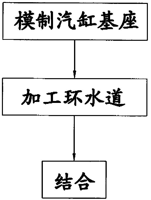
[0040] First, see figure 1 , 2 , Shown in 4,6, is the schematic flow sheet of water-cooled locomotive cylinder method of the present invention, and its steps are as follows:

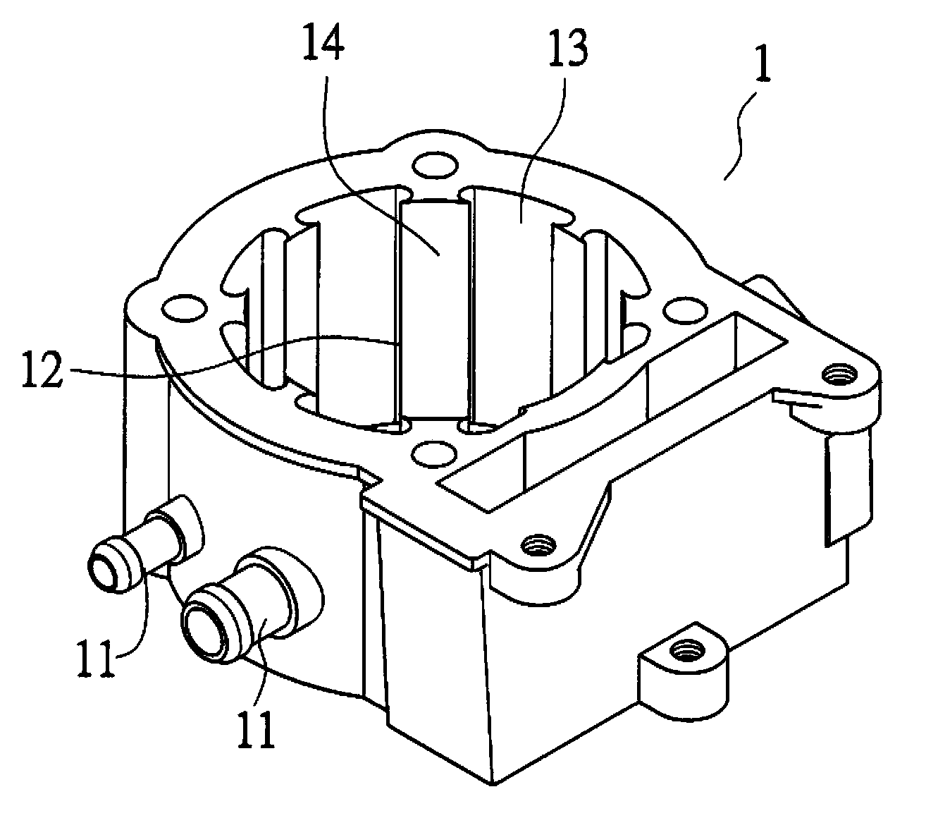
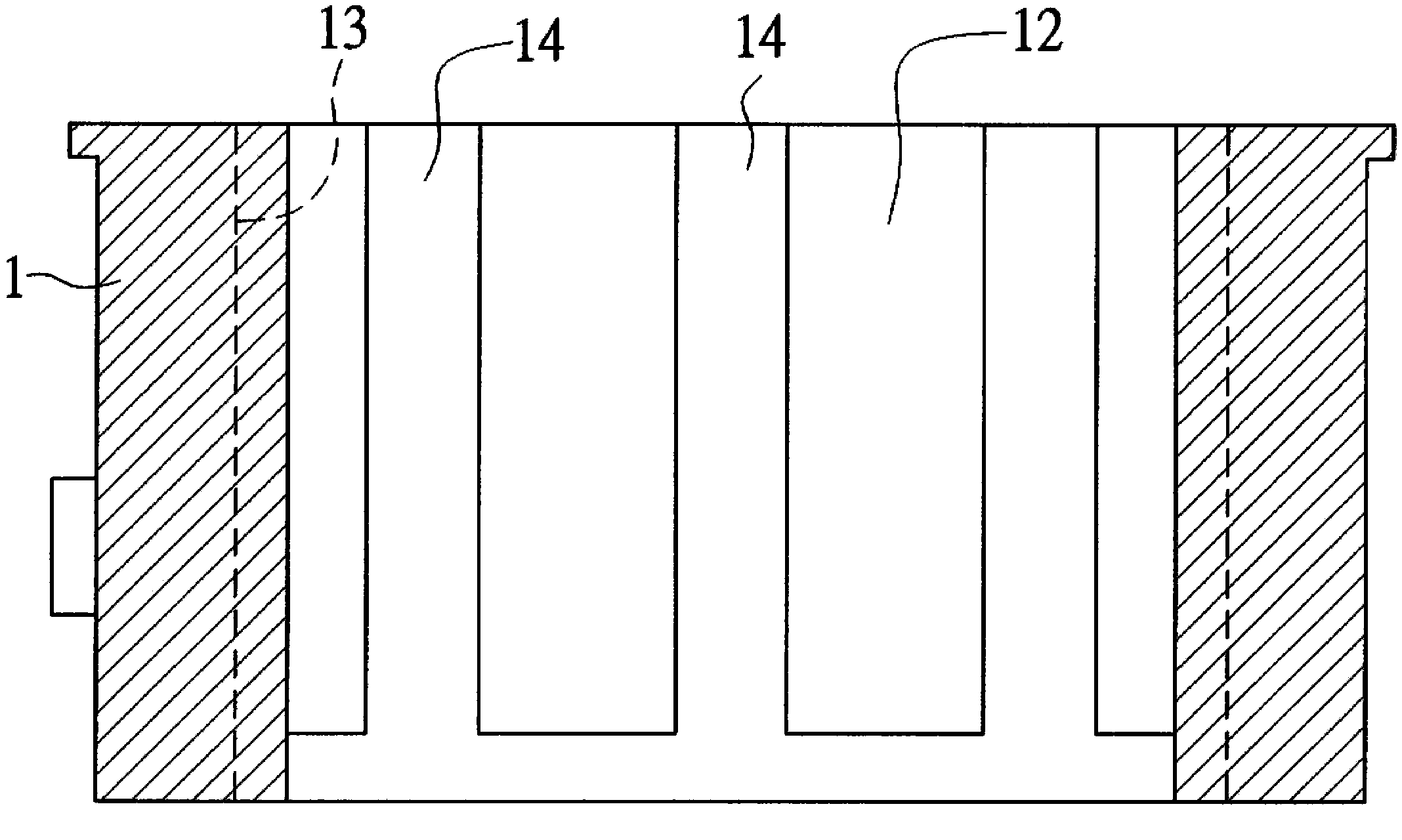
[0041] A. Molded cylinder base - A cylinder base 1 is molded. The cylinder base 1 has water inlet and outlet holes 11, and a through channel 12 is formed in the center, and a water flow channel is formed around the channel 12. 13, and a protruding wall-adhering section 14 is formed between two adjacent water flow channels 13; the above-mentioned water flow channel 13 is directly provided with a mold core in the mold and molded.

[0042] B. Machining the ring water channel - at the central channel 12 of the cylinder base 1, a ...


PUM


Abstract

The invention relates to a method for manufacturing a water-cooled locomotive cylinder. The method for manufacturing the water-cooled locomotive cylinder mainly comprises the steps that a cylinder basic early form with water flow channels and wall adherence sections is formed by manufacturing a cylinder base through a die, parts of the wall adherence sections are removed through the machining of water surrounding channels so that the wall adherence sections and the water flow channels can form spaces allowing cooling water to circulate, and lastly a piston wall pipe is correspondingly combined in the cylinder base. Therefore, the manufacturing of the cylinder is completed through the process, the simplification of the manufacturing process, the reduction of manufacturing cost and the reduction of manufacturing time are achieved, and meanwhile a good heat transmission effect is achieved.

Description

technical field [0001] The present invention relates to a manufacturing method of a water-cooled locomotive cylinder, in particular to a water-cooled locomotive cylinder that can reduce manufacturing cost and timeliness by prefabricating a water flow channel to achieve the effect of subsequent convenient processing and forming. method. Background technique [0002] The operation of general vehicles, such as locomotives, all-terrain vehicles, etc., is to mix the fresh air and fuel from the outside into oil and gas, and then input the oil and gas into the engine to burn and explode to generate power, and push the piston to reciprocate, and drive the belt through the crankshaft The speed change mechanism is used for transmission to achieve the purpose of traveling. [0003] And the engine can be divided into two kinds of air-cooled engine and water-cooled engine because of different heat dissipation methods, wherein, the known water-cooled engine is mainly provided with a cyli...

Claims


Application Information

Patent Timeline
Patent Type & Authority Applications(China)
IPC IPC(8): B23P15/00F02F1/14
CPCB23P15/00F02F1/14
Inventor 黄奕鈜
Owner COLIS INDAL
Why Eureka
Try Eureka