
Numerical control ultrasonic shot peening process method based on dynamic pressure signal adjustment

A dynamic pressure and signal adjustment technology, applied in the field of forming or shape correction, strength ultrasonic shot peening, can solve problems such as sheet metal deformation

Inactive Publication Date: 2014-01-22
NANJING UNIV OF AERONAUTICS & ASTRONAUTICS
View PDF4 Cites 7 Cited by
  • Summary
  • Abstract
  • Description
  • Claims
  • Application Information

AI Technical Summary

Problems solved by technology

[0004] In order to solve the problems in the development of CNC ultrasonic shot peening technology, this patent proposes a process method for ultrasonic shot peening strengthening, forming or shape correction of complex workpieces using ordinary three-axis CNC machine tools
The purpose of the present invention is to convert the intensity of ultrasonic shot peening into the pressure signal of the impact pin on the horn, monitor it, compare and analyze it with the specified pressure signal, drive the servo motor to control the lifting of the workbench, and make the pressure signal real-time Approaching the specified pressure signal to achieve the purpose of equal-intensity shot peening; at the same time, the invention proposes an adaptive dynamic clamping device to solve the clamping problem during the deformation and extension of the sheet metal

Method used


Image

  • Numerical control ultrasonic shot peening process method based on dynamic pressure signal adjustment
  • Numerical control ultrasonic shot peening process method based on dynamic pressure signal adjustment
  • Numerical control ultrasonic shot peening process method based on dynamic pressure signal adjustment

Examples


Embodiment Construction

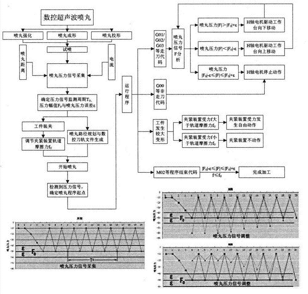
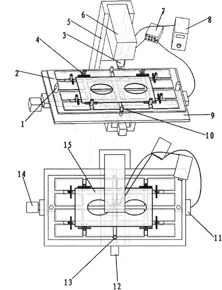
[0033] This example adopts the CNC ultrasonic shot peening process for the overall aviation structural parts. The overall process flow of the process is as follows figure 1 As shown, the clamping before shot peening processing is as follows figure 2 Shown: On the basis of the original three-axis CNC machine tool (parts 5, 6, 9, 12, and 14 in the figure), a "T"-shaped slot lifting table 2 that can move up and down is added, controlled by the H-axis closed-loop servo drive 11 The movement of the lifting platform in the Z-axis direction is ensured by the cooperation of the guide post and guide sleeve (10, 13) to ensure its relative motion accuracy; the dynamic signal test and analysis system 7 monitors, analyzes and calculates the shot peening pressure in the ultrasonic shot peening tool head 3 in real time Signal, the calculation result is sent to the H-axis servo drive 11 as the drive signal; eight dynamic clamping devices 4 are used to clamp and fix the edge of the workpiece ...


PUM


Abstract

The invention provides a numerical control ultrasonic shot peening process method based on dynamic pressure signal adjustment, and belongs to the technical field of shot peening machining. The method is based on a common three-axis numerical control machine tool, impact force formed after a striker impacts on the surface of a material and rebounds in the ultrasonic shot peening process serves as a monitoring signal, and the difference between a real-time pressure signal and a specific signal is analyzed by means of a ceramic capacitance pressure sensor and a pressure dynamic measuring system so that a lifting worktable servo motor is driven to move to enable the pressure signal to be close to the specific signal, and therefore the impact force borne by the material in a shot peening area keeps stable; in the deformation process of a workpiece to be peened, the workpiece overcomes extension or contraction of rubber friction needed by moving of a dynamic clamping device in the X direction, the Y direction and the Z direction, so that the clamping device is suitable for the spatial position of a clamping point of the workpiece to be peened in real time. According to the method, peening strength of each area is consistent with a theoretical value specified by the process, the high-precision peening forming and strengthening effects are achieved, and the method has high feasibility and practicality in peening machining of large aviation structural components.

Description

technical field [0001] The invention relates to the field of advanced shot-peening technology, in particular, it can carry out equal-intensity ultrasonic shot-peening strengthening, forming or shape-correction on integral shot-peening workpieces with complex geometric features. Background technique [0002] Ultrasonic shot peening (USP) is a new type of surface modification method. This technology uses ultrasonic vibration mechanical energy to drive projectiles or colliders to hit the metal surface at high speed, so that the impacted surface and its underlying metal materials are plastically deformed and extended, and the residual material is introduced. It is an advanced shot peening forming and strengthening process that gradually causes the plate to bend and deform toward the sprayed surface to achieve the desired shape while compressing the stress. Compared with traditional shot peening, ultrasonic shot peening can obtain greater hardened layer depth and compressive stre...

Claims


Application Information

Patent Timeline
IPC IPC(8): B24C1/10
Inventor 鲁世红郭超亚刘朝训朱一枫
Owner NANJING UNIV OF AERONAUTICS & ASTRONAUTICS
Learn More