A feeding hopper with material crushing function

A material crushing and feeding hopper technology, which is applied in the direction of grain processing, etc., can solve the problems of plastic extruder screw and barrel, which have a great impact on the service life, material blockage, and difficulty in melting processing.

Active Publication Date: 2016-03-30
NANTONG BAILONG ORGANIC FERTILIZER TECH
View PDF2 Cites 0 Cited by
  • Summary
  • Abstract
  • Description
  • Claims
  • Application Information

AI Technical Summary

Problems solved by technology

However, after the material enters the feeding hopper, it is no longer crushed, which makes it difficult to melt the material after entering the extruder, and the screw in the barrel is also difficult. The material with large particles is pushed smoothly, which increases the difficulty of extruding the extruder
At the same time, due to the accumulation of a large amount of material in the feeding hopper, this feeding method is likely to cause the material blockage at the outlet of the feeding hopper, forming a "bridging" phenomenon, which in turn affects the normal feeding of the feeding hopper, thus causing the plastic extruder to break. The material is idling, and the production cannot continue. At the same time, it has a great impact on the service life of the screw and barrel of the plastic extruder. The manufacturer must equip a special person to stir in the hopper, and the feeding effect fluctuates greatly.
However, the existing forced-feeding adopts the spiral downward pressure type, and the screw downward pressure structure is used in the feeding hopper, which not only often gets stuck due to the uneven size of the material, but also consumes a lot of energy during the long-distance screw pressing process. It is easier to cause the temperature in the feeding hopper to rise and make the material sticky and difficult to feed

Method used


Image

  • A feeding hopper with material crushing function
  • A feeding hopper with material crushing function
  • A feeding hopper with material crushing function

Examples


Embodiment Construction

[0021] The technical solutions of the present invention will be further described below in conjunction with the accompanying drawings and through specific implementation methods.

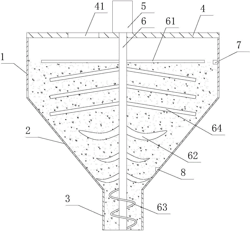
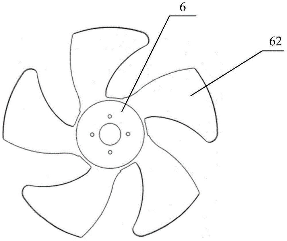
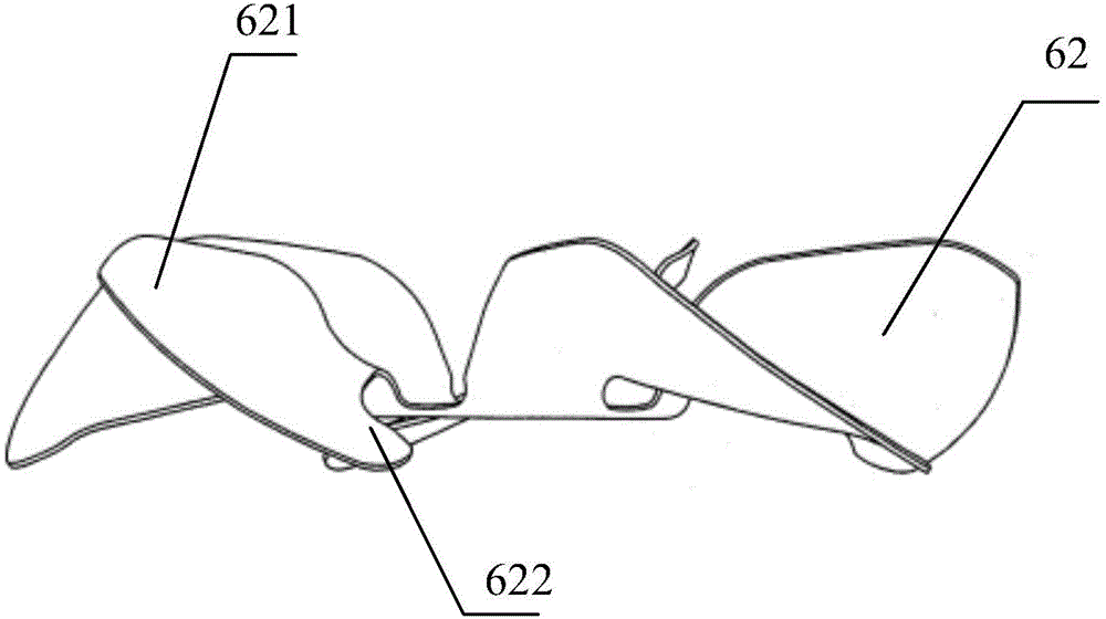
[0022] like Figures 1 to 3 As shown, a feeding hopper with material crushing function includes a bucket body, the bucket body includes an inverted conical storage section 2 and a circular discharge section 3, the storage section 2 and the discharge section 3 are the same Shaft setting; the top of the storage section 2 is provided with a cover plate 4, the cover plate 4 is provided with a feed port 41, the top of the cover plate 4 is provided with a drive motor 5, and the drive motor 5 is connected to a main shaft 6 that extends into the inside of the bucket body The main shaft 6 is provided with multiple groups of material crushing devices and multiple groups of loose blade structures at intervals. The material crushing device is located above the loose blade structure, and the material crushing de...


PUM


Abstract

The invention discloses a feeding hopper with function of fragmenting materials. The feeding hopper comprises a hopper body. The hopper body comprises a material storage section and a material discharging section, which are coaxially arranged. The top of the material storage section is provided with a cover plate; the cover plate is provided with a feed port; the top of the cover plate is provided with a driving motor; the driving motor is connected with a main shaft extending into the hopper body; a plurality of material crushing device groups and a plurality of loose blade structures are arranged at interval on the main shaft; the material crushing devices are above the loose blade structures; and material crushing devices and the loose blade structures are arranged on the material storage section. Each group of material crushing device comprises a plurality of blades arranged in an umbrella shape; each group of loose blade structure includes at least 4 loose blades uniformly arranged in annular shape. Each loose blade is obliquely arranged, and the surface of each loose blade is arranged towards the rotation direction of the main shaft. The end of the main shaft is provided with spiral blades, which are located at the discharging section. The feeding hopper can rapidly fragment material with large particles and is convenient for extrusion of an extruder.

Description

technical field [0001] The invention relates to the technical field of extruder equipment, in particular to a feeding hopper with material crushing function. Background technique [0002] The host of the plastic extruder is the extruder, which consists of an extrusion system, a transmission system and a heating and cooling system. At present, the automatic metering system is used for feeding the plastic extruder. The plastic and powder are stored in the large feeding hopper, and the stored material is fed to the extrusion equipment through the automatic metering system. In principle, as long as there is material in the feeding hopper, production can be done. Continuous, so keeping the feed hopper filled is critical. The existing feeding hopper has a large volume, and a large amount of materials can be poured in at one time, and enter into the feeding port of the plastic extruder from top to bottom by utilizing the gravity without power. However, after the material enters t...

Claims


Application Information

Patent Timeline
Patent Type & Authority Patents(China)
IPC IPC(8): B29C31/02B29C47/10B29C47/92B02C18/10B02C18/18B29C48/92
Inventor 吴镇宇
Owner NANTONG BAILONG ORGANIC FERTILIZER TECH
Why Eureka
Try Eureka