

Automatic screw rod feeding device
An automatic feeding and screw technology, applied in the direction of conveyor objects, transportation and packaging, etc., can solve the problems of poor screw effect and poor versatility, and achieve the effects of reducing labor intensity, accurate and reliable material distribution, and good adaptability
- Summary
- Abstract
- Description
- Claims
- Application Information
AI Technical Summary
Problems solved by technology
Method used
Image

Examples
Embodiment Construction
[0038] In order to make the object, technical solution and advantages of the present invention clearer, the present invention will be further described in detail below in conjunction with the accompanying drawings and embodiments. It should be understood that the specific embodiments described here are only used to explain the present invention, not to limit the present invention.
[0039] Embodiments of the present invention will be described in detail below in conjunction with specific drawings. For ease of description, the drawings only show relevant parts of the present application.
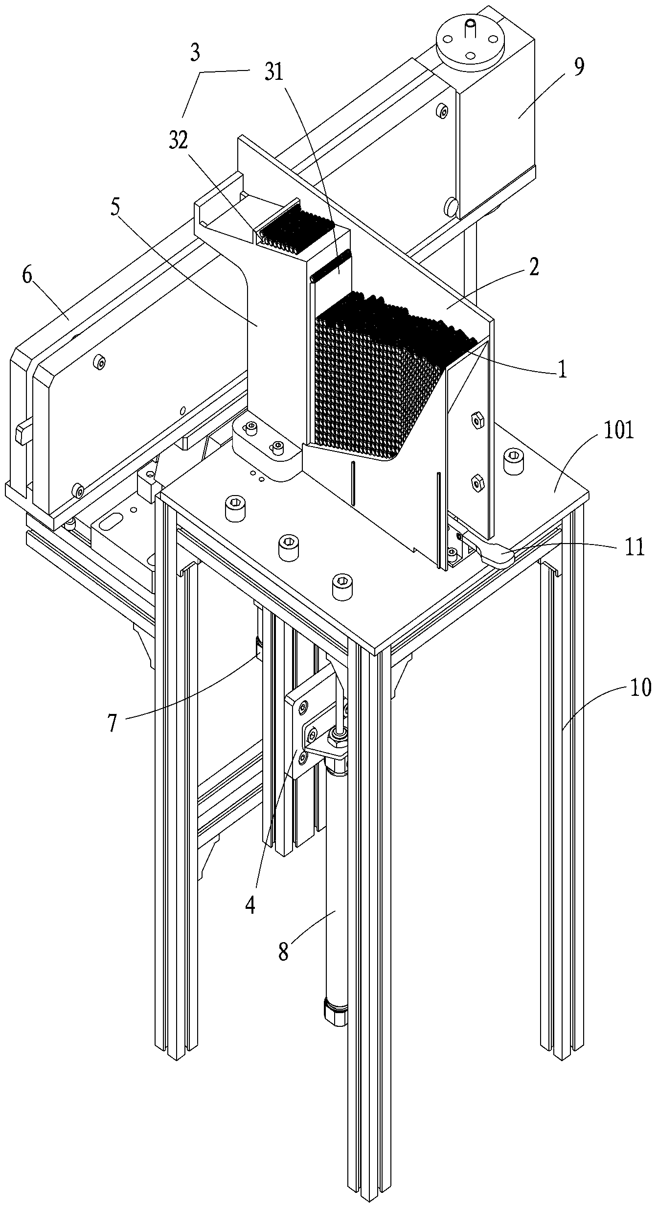
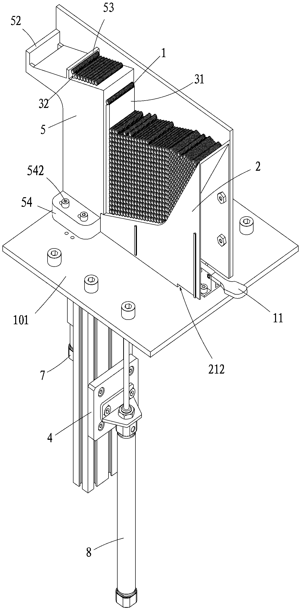
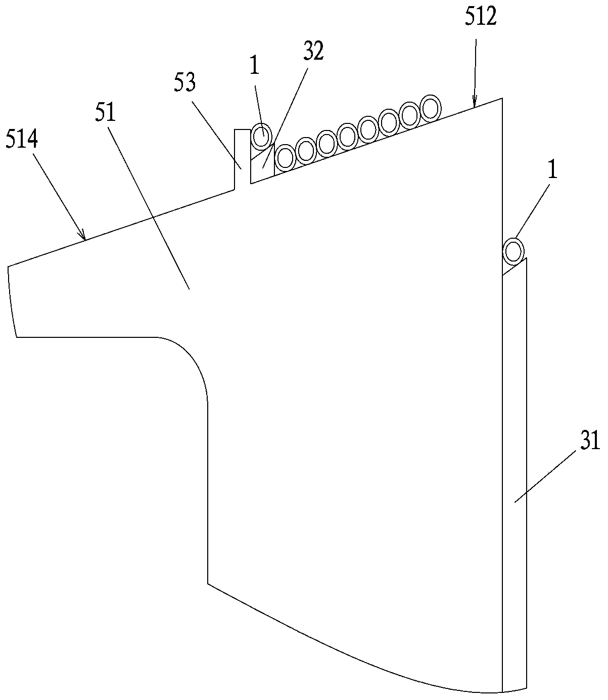
[0040] see Figure 1-9 , the invention provides an embodiment of a screw automatic feeding device, which includes:
[0041] Frame 10, as the carrier of each moving part and each connecting fixed part, it includes a frame body composed of four supporting feet 102 and a workbench 101 arranged horizontally on the top of the frame body;
[0042] At least one quick-change material box 2 is arra...
PUM
 Abstract
Description
Claims
Application Information