a heat exchanger

A technology for heat exchangers and inlet headers, applied in heat exchange equipment, evaporators/condensers, lighting and heating equipment, etc., can solve problems such as deformation of refrigerant pipes, reduce deformation, enhance heat transfer effects, and prevent deformation effect

Active Publication Date: 2016-08-10
JIANGSU TONGSHENG HEAT EXCHANGER
View PDF6 Cites 0 Cited by
  • Summary
  • Abstract
  • Description
  • Claims
  • Application Information

AI Technical Summary

Problems solved by technology

[0004] The technical problem to be solved by the present invention is to provide a special-shaped tube that can solve the deformation problem of the refrigerant tube, and a heat exchanger that adds support parts inside the special-shaped tube to prevent the deformation of the special-shaped tube

Method used


Image

  • a heat exchanger
  • a heat exchanger
  • a heat exchanger

Examples


Embodiment 1

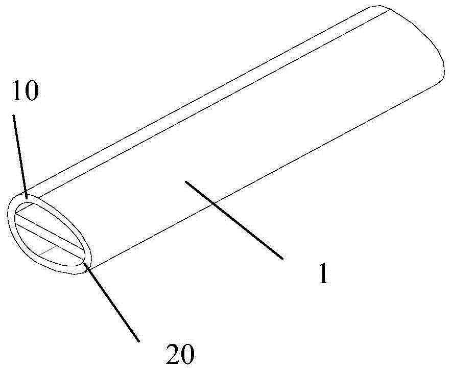
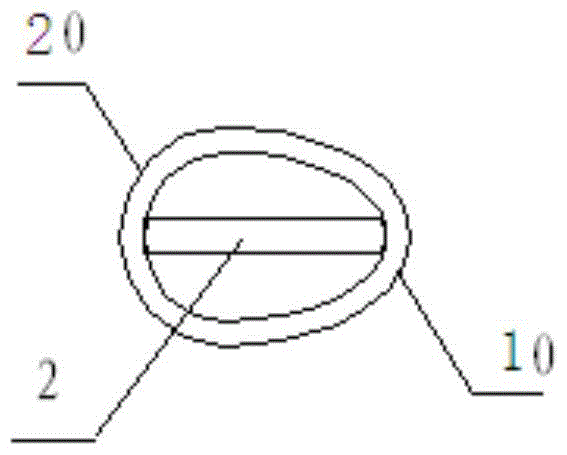
[0031] Embodiment 1: as figure 1 , figure 2 As shown, the special-shaped pipe 1 is formed by a windward end 10 and a leeward end 20, the windward end 10 is a half ellipse cut along the short axis of the ellipse, the leeward end 20 is a half circle, and the diameter of the circle is equal to that of the ellipse short diameter. During the heat exchange process, the high temperature makes the internal pressure of the elliptical tube continuously increase, and the pressure first acts on the tube wall at the windward end 10. The windward end 10 is a half ellipse cut along the short axis of the ellipse, and the half ellipse tends to become shorter. At this moment, the fan blows to the windward end 10 at first, so that the windward end 10 is cooled rapidly, the deformation is controlled on the half ellipse, and the overall deformation is reduced.

Embodiment 2

[0032] Embodiment 2: A support member 2 is provided along the axial direction of the special-shaped pipe in the long axis direction of the section of the inner hole of the special-shaped pipe 1 , and the support member 2 is in clearance fit with the inner wall of the special-shaped pipe. The support member is in the shape of a rectangular plate.

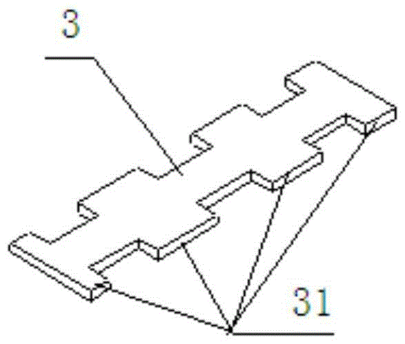
[0033] Such as image 3 As shown, the support member 2 is a continuous longitudinal I-shaped plate-shaped support 3, and the two sides of the I-shaped plate-shaped support 3 are formed with a flange portion 31 and a concave portion 32, and the gap between the flange portion 31 and the inner wall of the special-shaped pipe Cooperating, the cold medium can circulate up and down in the special-shaped pipe 1 through the I-shaped support member 3 through the recess 32 . The end of the supporting part abuts against the inner wall of the special-shaped pipe, and when the special-shaped pipe is heated, the windward end is deformed, and the ...

Embodiment 3

[0034] Embodiment 3: A support member 2 is provided along the axial direction of the special-shaped pipe along the axial direction of the special-shaped pipe 1 in the direction of the major axis and the short axis of the section of the inner hole of the special-shaped pipe, and the support member 2 is in clearance fit with the inner wall of the special-shaped pipe. The supporting part is a cross structure.

[0035] Such as Figure 4 -shown in -6, the support member 2 is a cross plate-shaped support 4, and the cross plate-shaped support 4 is composed of two symmetrical short sides and asymmetrical long and short sides; two symmetrical short sides and asymmetrical long and short sides The short sides in the center respectively correspond to the three end faces that support the inner wall of the leeward end 20 of the special-shaped pipe, and the two symmetrical short sides and the long side of the asymmetrical long and short sides support the end face of the inner wall of the win...


PUM


Abstract

The invention discloses a heat exchanger, which comprises: an inlet header, an outlet header, a close-stacked flap arranged between the inlet header and the outlet header, and a connecting member that passes through the flap and connects the inlet header and the outlet header. A special-shaped pipe, the special-shaped pipe is formed by a windward end and a leeward end, the windward end is a half ellipse cut along the short axis of the ellipse, the leeward end is a half circle, and the diameter of the circle is equal to the short diameter of the ellipse. A supporting component is arranged in the inner hole of the special-shaped tube along the radial direction of the special-shaped tube, and the supporting component is in clearance fit with the inner wall of the special-shaped tube. The support members include continuous longitudinal I-shaped, cross-shaped and triangular tubular struts. Beneficial effects of the present invention: the special-shaped pipe structure controls the deformation on half an ellipse, reducing the overall deformation; the supporting part is installed in the special-shaped pipe, and the pipe wall at the end of the long axis is supported by the support plate to prevent the deformation of the special-shaped pipe; The through-hole of the cooling medium plays the role of turbulence and enhances the heat exchange effect.

Description

technical field [0001] The invention relates to the field of air conditioning, in particular to a heat exchanger for refrigeration and air conditioning. Background technique [0002] Generally speaking, in refrigeration equipment such as air conditioners, compressors, condensers, expansion valves, and evaporators form a refrigeration cycle system, and heat exchange devices such as condensers and evaporators are collectively referred to as heat exchangers. In the heat exchanger, the refrigerant changes from liquid to gas or from gas to liquid to exchange heat with the surrounding air, that is, to absorb heat or release heat, so as to achieve the cooling effect. The heat dissipation effect of the heat exchange device will directly affect the refrigeration energy efficiency of the entire refrigeration equipment. [0003] The traditional heat exchange device uses coiled tubes and heat dissipation fins set on the coils to exchange the heat of the medium in the tube with the outs...

Claims


Application Information

Patent Timeline
Patent Type & Authority Patents(China)
IPC IPC(8): F25B39/00F28F1/02
Inventor 不公告发明人
Owner JIANGSU TONGSHENG HEAT EXCHANGER
Why Eureka
Try Eureka