Supercharge Your Innovation With Domain-Expert AI Agents!

Microbubble-generating device, microbubble-generating method, and gas-liquid reaction method using same

A bubble generating device and technology for generating bubbles, which are applied in the direction of film-type liquid-gas reaction, gas/vapor and liquid mixing, mixers with rotary stirring device, etc. Efficiency effect of gas-liquid reaction

Active Publication Date: 2014-01-22
M TECH CO LTD
View PDF10 Cites 4 Cited by
  • Summary
  • Abstract
  • Description
  • Claims
  • Application Information

AI Technical Summary

Problems solved by technology

[0005] However, in the fluid processing device described in Patent Document 4 or Patent Document 5, there has been no specific disclosure for generating micro-bubbles between the processing surfaces so far. A method that utilizes generated microbubbles

Method used


Image

  • Microbubble-generating device, microbubble-generating method, and gas-liquid reaction method using same
  • Microbubble-generating device, microbubble-generating method, and gas-liquid reaction method using same
  • Microbubble-generating device, microbubble-generating method, and gas-liquid reaction method using same

Examples


Embodiment 1~4

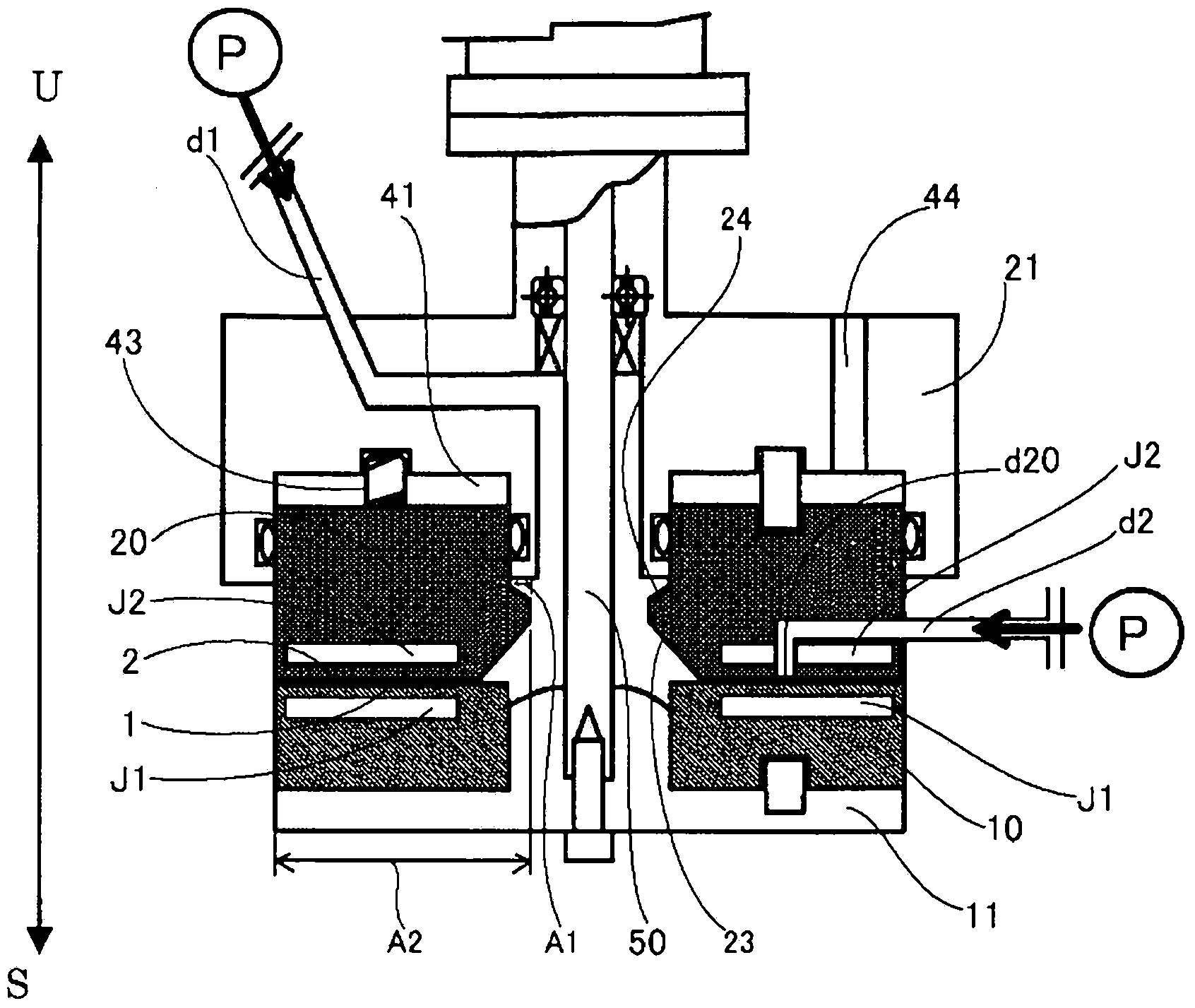
[0087] The liquid sodium hydroxide solution as the first fluid is fed from the center at the supply pressure = 0.30 MPaG and the rotation speed in Table 1, and at the same time, carbon dioxide gas (carbon dioxide gas) as the second fluid gas is introduced at 25°C. Between surfaces 1 and 2, the first fluid and the second fluid are mixed in the film fluid. The feeding temperatures of the first fluid and the second fluid were measured by measuring the respective temperatures of the first fluid and the second fluid immediately before being introduced into the processing apparatus (more specifically, immediately before being introduced between the processing surfaces 1 and 2). The liquid containing sodium bicarbonate is discharged from the treatment surfaces 1, 2. The liquid containing the discharged sodium bicarbonate was dried and solidified in an evaporator, and thermally decomposed to change the sodium bicarbonate into sodium carbonate. Thereafter, the amount of sodium carbona...

Embodiment 5~8

[0094] From the center, the SDS aqueous solution as the liquid of the first fluid is fed at the supply pressure = 0.30 MPaG and the rotation speed of Table 2, and at the same time, nitrogen gas as the gas of the second fluid is introduced at 25°C between the processing surfaces 1 and 2. The first fluid and the second fluid are mixed in the thin film fluid. The feeding temperatures of the first fluid and the second fluid were measured by measuring the respective temperatures of the first fluid and the second fluid immediately before being introduced into the processing apparatus (more specifically, immediately before being introduced into the space between the processing surfaces 1 and 2). The liquid containing fine bubbles of nitrogen gas is discharged from the processing surfaces 1 and 2 . The liquid containing the discharged nitrogen gas was observed with an optical microscope to confirm the bubble particle size of nitrogen gas.

[0095] [Table 2]

[0096]

[0097] As c...


PUM


Abstract

The present invention addresses the problem of: providing a device and method for generating microbubbles in a plurality of processing surfaces in a plurality of processing units disposed in opposition so as to be capable of being brought together and moved apart, at least one being capable of relative rotation with respect to the other; as well as providing a gas-liquid-reaction method using the microbubble-generating method. Provided are: a plurality of processing units (10, 20) disposed in opposition so as to be capable of being brought together and moved apart, at least one being capable of relative rotation with respect to the other; processing surfaces (1, 2) provided in mutually opposed positions in the respective processing units (10, 20); and at least two independent flow channels (d1, d2) communicating with the space between the processing surfaces (1, 2). A gas and a liquid representing a fluid to be processed are introduced into the space between the processing surfaces (1, 2) from the at least two independent flow channels (d1, d2), and the fluid is processed. The liquid is introduced from one flow channel (d1) of at least two independent flow channels (d1, d2), and the gas is introduced through the other flow channel (d2), whereby bubbles are generated between the processing surfaces (1, 2).

Description

technical field [0001] The invention of the present application relates to a device for generating microbubbles between processing surfaces in a processing unit in which at least one of the approaching and separating parts is relatively rotated relative to the other, and a method for generating microbubbles. It also relates to a gas-liquid reaction method in which a gas-liquid reaction occurs by bringing microbubbles generated between the above-mentioned processing surfaces into contact with a reactant. Background technique [0002] Micro-bubbles such as micro-bubbles and nano-bubbles are widely used in aquaculture, water treatment, soil purification, reduction of fluid resistance at the bottom of ships, sterilization, use of contrast agents, environmental fields, industrial fields, health fields, medical fields, etc. It has been applied in many fields and has attracted much attention in recent years. [0003] As a device for generating such micro-bubbles, generally, it is ...

Claims


Application Information

Patent Timeline
Patent Type & Authority Applications(China)
IPC IPC(8): B01F3/04B01F5/22B01F7/26B01J10/02B01F25/74B01F27/93
CPCB01J19/1887B01F23/233B01F23/2373B01F27/2712B01F27/2714B01F23/00B01F23/20B01F25/00B01F25/74B01F27/00B01F27/93B01F23/231B01F23/2319C01D7/07
Inventor 榎村真一
Owner M TECH CO LTD
Features
  • R&D
  • Intellectual Property
  • Life Sciences
  • Materials
  • Tech Scout
  • Unparalleled Data Quality
  • Higher Quality Content
  • 60% Fewer Hallucinations
Learn More