Air intake structure for internal combustion engine

A technology of internal combustion engine, construction, applied in the direction of fuel air intake, internal combustion piston engine, combustion engine

Active Publication Date: 2014-01-22
TOYOTA JIDOSHA KK
View PDF6 Cites 10 Cited by
  • Summary
  • Abstract
  • Description
  • Claims
  • Application Information

AI Technical Summary

Problems solved by technology

[0005] However, when the intake air temperature is low, for example, when the outside air temperature is low and the engine is idling, moisture contained in the blow-by gas may be deposited on the inner wall surface of the intake pipe at the connection of the PCV pipe. freezes near the top and grows into larger ice cubes

Method used


Image

  • Air intake structure for internal combustion engine
  • Air intake structure for internal combustion engine
  • Air intake structure for internal combustion engine

Examples


Embodiment Construction

[0037] Hereinafter, preferred embodiments for carrying out the present invention will be described in detail with reference to the drawings.

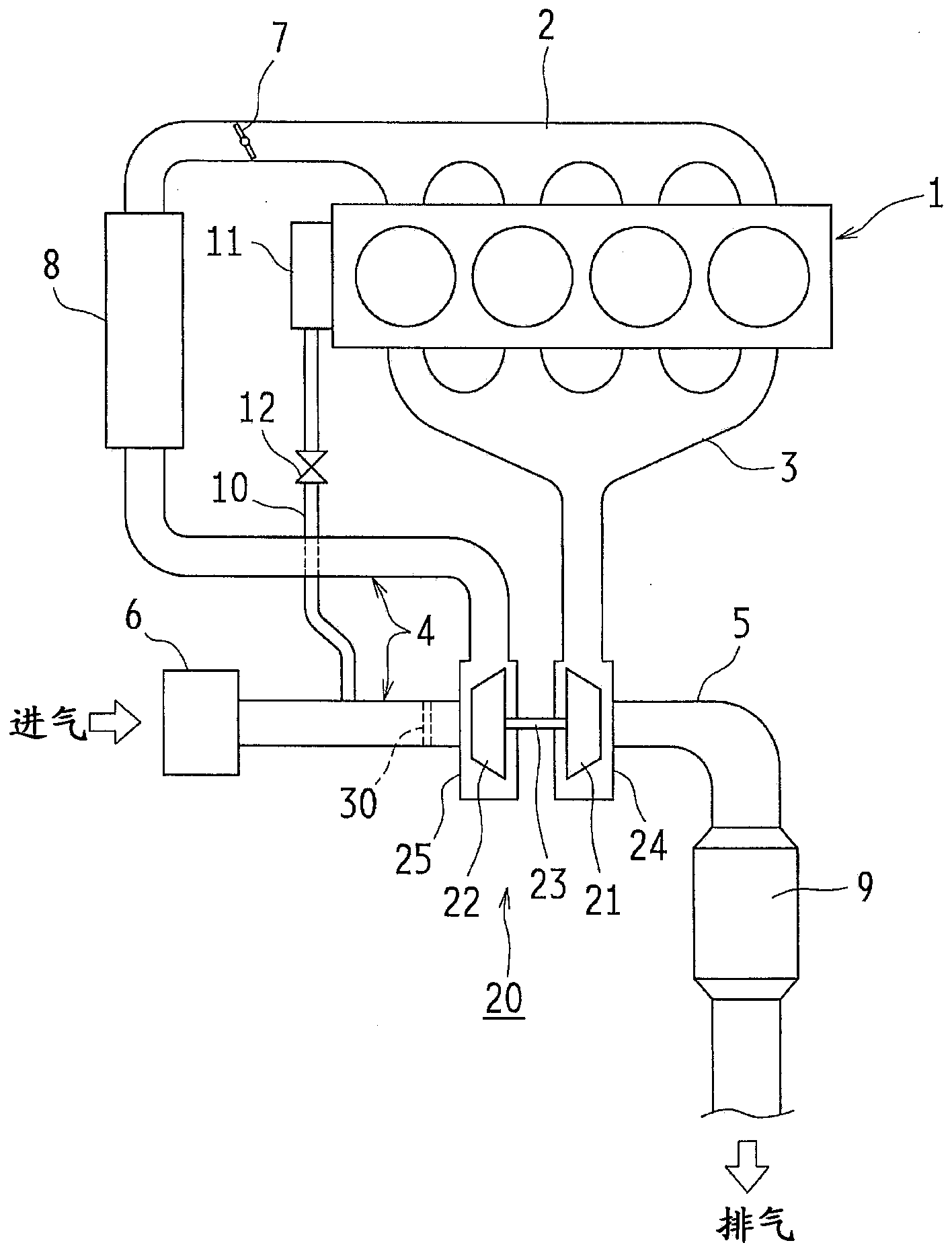
[0038] Figure 1 to Figure 3 One embodiment of the present invention is shown. The engine 1 illustrated in this embodiment is, for example, an inline four-cylinder. An intake manifold 2 for distributing and supplying intake air to each cylinder and an exhaust manifold 3 for collecting exhaust gas discharged from each cylinder are attached to a cylinder head (not shown) of the engine 1 .

[0039] An intake pipe 4 for taking in air from the atmosphere is connected to the intake manifold 2 . An air cleaner 6 is installed at the inlet of the intake pipe 4 . The intake manifold 2 and the intake pipe 4 constitute an intake passage.

[0040] In addition, a throttle valve 7 for adjusting the intake air amount of the engine 1 is provided on the intake manifold 2 on the upstream side in the flow direction of intake air. The throttle valve 7 ...


PUM


Abstract

The invention provides an air intake structure of an internal combustion engine (1), for which the compressor impeller (22) of a turbocharger (20) is provided in an air intake passage (4) of the internal combustion engine (1), the present invention addresses the problem of ensuring that blocks of ice (15) that have formed on the inner wall surface of the air intake passage (4) do not collide with the compressor impeller (22) and particularly with the blades (22a) when these blocks of ice (15) peel away, as opposed to preventing the formation of the blocks of ice (15) on the inner wall surface of the air intake passage (4). A trapping member (30) for trapping blocks of ice (15) that have formed on the inner wall surface of the air intake passage (4) when the blocks of ice (15) peel away is provided upstream from the compressor (22) impeller in the air intake passage (4).

Description

technical field [0001] The present invention relates to an intake structure of an internal combustion engine in which a compressor wheel of a turbocharger is provided in an intake passage of the internal combustion engine. Background technique [0002] For example, in an internal combustion engine (engine) mounted on a vehicle, unburned air-fuel mixture and / or burnt combustion gas may leak from the combustion chamber into the crankcase through the gap between the cylinder and the piston. [0003] If the combustion gas is mixed with the engine oil in the crankcase, the engine oil will be deteriorated, so in order to prevent the deterioration of the engine oil, the engine is equipped with a PCV (Positive Crankcase Ventilation) blow-by system that ventilates the inside of the crankcase. Leakage gas reduction device. [0004] In an engine equipped with this blow-by gas reduction device, the blow-by gas in the crankcase passes through the oil separator and is separated into gas ...

Claims


Application Information

Patent Timeline
Patent Type & Authority Applications(China)
IPC IPC(8): F02B39/00F02M35/10
CPCF02B39/16F02B37/00F02M35/10262F02M25/06F01M13/022F01M2013/027F02M35/10222F02M35/0216F02M35/046F02M35/088F02M35/10157Y02T10/12F02B33/02
Inventor 五十岚修
Owner TOYOTA JIDOSHA KK
Why Eureka
Try Eureka