

Method for prolonging service life of twist drill based on heat pipe phase changes
A twist drill and heat pipe technology, applied in twist drills, repair drills, drilling tool accessories, etc., can solve problems such as patents that have not yet been seen, and achieve the effects of reducing manufacturing costs, cutting temperature, and high heat transfer efficiency
- Summary
- Abstract
- Description
- Claims
- Application Information
AI Technical Summary
Problems solved by technology
Method used
Image

Examples
Embodiment 1
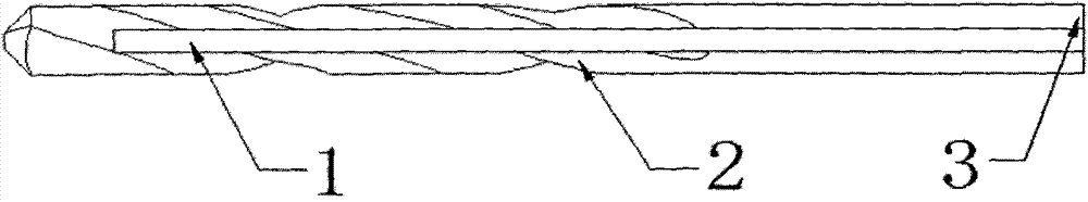
[0038] Such as image 3Shown, the schematic diagram of the wear state of the twist drill flank under different service conditions, wherein: the diameter of the twist drill used in the experimental measurement is 3mm; CF-Block (1-3) represents respectively: when using cutting fluid, the twist drill of the present invention Schematic diagram of the wear condition of the cutter face; HF-Block (1-3) represents respectively: when using the heat pipe 1, the schematic diagram of the wear condition of the flank of the twist drill of the present invention; Block (1-3) represents: 3 pieces of workpieces used in the experimental measurement .
[0039] The measurement results show that under the same processing conditions, the flank wear of the twist drill using heat pipe 1 is lighter than that of the twist drill using cutting fluid.
[0040] In addition, the cutting fluid used in this experiment is the cutting oil commonly used in the manufacturing industry.
Embodiment 2
[0042] Such as Figure 4 As shown, the schematic diagram of the service life of the twist drill under different conditions of use, in which: the diameter of the twist drill used in the experimental measurement is 10mm; SD means: the situation without using cutting fluid and heat pipe 1; CF means: the situation using cutting fluid; HF means: The case of using heat pipe 1.
[0043] The measurement results show that: under the same processing conditions, the life of the twist drill cooled by the heat pipe 1 is longer than that of the twist drill using cutting fluid.
[0044] In addition, the cutting fluid used in this experiment is the cutting oil commonly used in the manufacturing industry.
Embodiment 3
[0046] Such as Figure 5 As shown, the schematic diagram of the twist drill processing temperature changing with time under different conditions of use, where: the diameter of the twist drill used in the experimental measurement is 20mm; SD means: the situation without using cutting fluid and heat pipe 1; CF means: the situation using cutting fluid; HF means: the case of using heat pipe 1; the subscripts 1 and 2 respectively indicate the number of twist drills under different cooling conditions.
[0047] The measurement results show that: under the same processing conditions, the temperature of the cutting part of the twist drill when the heat pipe 1 is used for cooling is lower than that of the cutting part of the twist drill when the cutting fluid is used.
[0048] In addition, the cutting fluid used in this experiment is the cutting oil commonly used in the manufacturing industry.
PUM
| Property | Measurement | Unit |
|---|---|---|
| Diameter | aaaaa | aaaaa |
Abstract
Description
Claims
Application Information