High-frequency quenching process of n-type collision pin

A high-frequency quenching and process technology, applied in the field of high-frequency quenching, can solve problems such as ∏-shaped knock pin cracks, easy to break, and easy to cause traffic accidents, and achieve the effects of improving efficiency, improving safety performance, and excellent performance

Active Publication Date: 2014-01-29
上海朋泰机械科技有限公司
View PDF5 Cites 3 Cited by
  • Summary
  • Abstract
  • Description
  • Claims
  • Application Information

AI Technical Summary

Problems solved by technology

However, the Π-shaped striker pin quenched by this process has microcracks after quenching, and i

Method used


Image

  • High-frequency quenching process of n-type collision pin
  • High-frequency quenching process of n-type collision pin

Examples


Embodiment Construction

[0010] The present invention will be further described below in conjunction with specific embodiments. It should be understood that the following examples are only used to illustrate the present invention but not to limit the scope of the present invention.

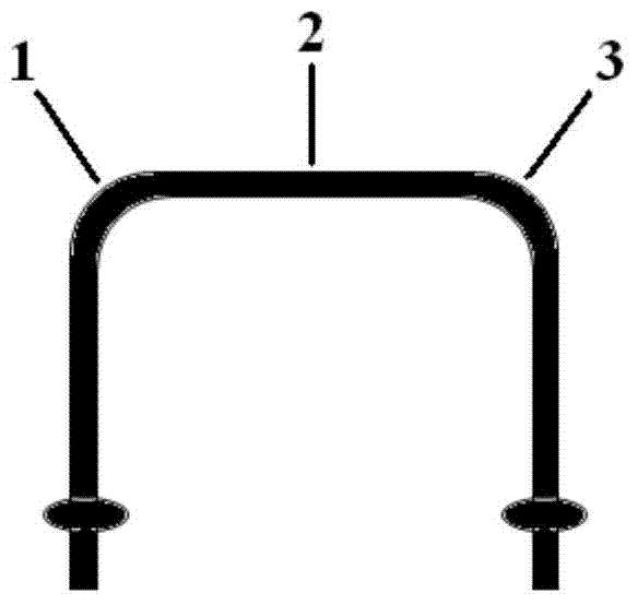
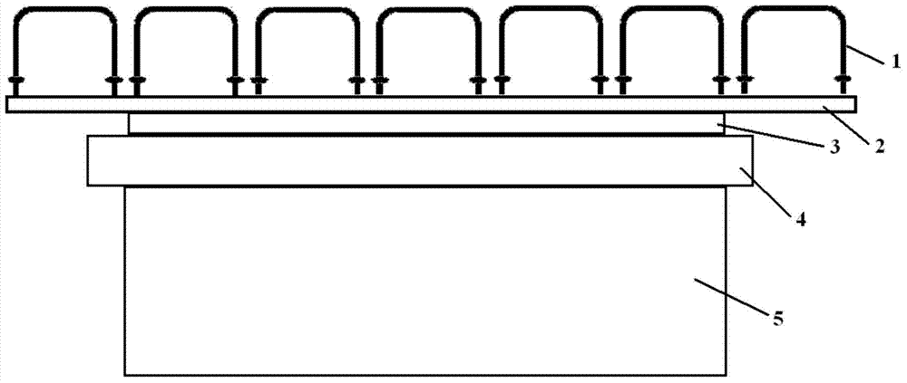
[0011] The production equipment model of the present invention is GGC80-2A for high-frequency quenching of ∏-shaped striker pins, the frequency is 250kHz, and the process flow is: placement→heating→oil quenching→tempering. Placement: Up to 7 parts can be placed on the quenching machine for high-frequency quenching at the same time. The schematic diagram of placement is as follows figure 2 shown. Heating: The temperature is 880-900°C, the ascent speed of the quenching machine is 125mm / min, the cathode voltage is 7.5kV, the anode current is 5A, and the grid current is 0.5A. When the sensor rises to the two fillets, it stays for 0.1s. To ensure even heating when heated to this place. Oil Quenching: Cool the heated parts ...


PUM


Abstract

The invention discloses a high-frequency quenching process of an n-type collision pin. The process comprises the following steps: putting; heating; oil quenching; and tempering. Through treatment of the process disclosed by the invention, various performances of the n-type collision pin are excellent through detection without rupture phenomenon, thereby improving the safety performance to a greater extent.

Description

technical field [0001] The invention belongs to the field of high-frequency quenching, in particular, it relates to a high-frequency quenching process for ∏-shaped knockout pins. Background technique [0002] The Π-type striker pin is often used in automobile structures, the material is 35CrMo, the upper part is quenched at 29-32HRC, and the structure is as follows figure 1 shown. In the prior art, the high-frequency quenching process of the Π-shaped striker pin is as follows: (1) high-frequency quenching at a temperature of 880-900°C; (2) spraying water and cooling to room temperature; (3) tempering at 560°C. However, the ∏-shaped striker pin quenched by this process has microcracks after quenching, and it is easy to break at the two rounded corners during use, which is easy to cause traffic accidents. Therefore, there is an urgent need to improve the existing high-frequency quenching process of the ∏-shaped striker, so as to achieve the purpose that the hardness of the ∏...

Claims


Application Information

Patent Timeline
IPC IPC(8): C21D1/673C21D1/42C21D9/00
CPCY02P10/25
Inventor 潘诗良
Owner 上海朋泰机械科技有限公司
Why Eureka
Try Eureka