Round Seal Piston Ring Assemblies

A technology for sealing piston and ring components, applied to piston rings, engine components, machines/engines, etc., can solve the problems of emission pollution, increased fuel consumption, hindering the functioning of piston rings, etc., and achieve the effect of simple manufacturing process

Inactive Publication Date: 2015-11-11
广州世喜科技有限公司
View PDF5 Cites 0 Cited by
  • Summary
  • Abstract
  • Description
  • Claims
  • Application Information

AI Technical Summary

Problems solved by technology

There are many deficiencies in the currently used piston rings: one is poor sealing. In order to ensure the normal operation of the piston ring in the cylinder and the piston ring groove, the piston ring needs to leave a necessary opening gap, which makes the gas in the cylinder leak through it to the crankshaft box, resulting in a decrease in fuel engine power, increased fuel consumption, and serious emission pollution; second, the positioning effect is not strong, and the forces acting on the piston ring include gas pressure, the ring's own elasticity, the inertial force of the ring's reciprocating motion, and the relationship between the ring and the cylinder and the ring groove. Due to the action of these forces, the ring will produce basic motions such as axial motion, radial motion, and rotary motion.
In addition, due to its motion characteristics, the piston ring will inevitably appear suspension and axial vibration caused by axial irregular motion, radial irregular motion and vibration, twisting motion, etc. along with irregular motion. Often prevents piston rings from functioning

Method used


Image

  • Round Seal Piston Ring Assemblies
  • Round Seal Piston Ring Assemblies
  • Round Seal Piston Ring Assemblies

Examples


Embodiment Construction

[0013] The technical solutions in the present invention will be clearly and completely described below in conjunction with the accompanying drawings in the present invention.

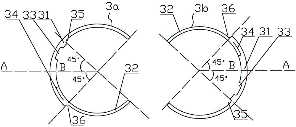
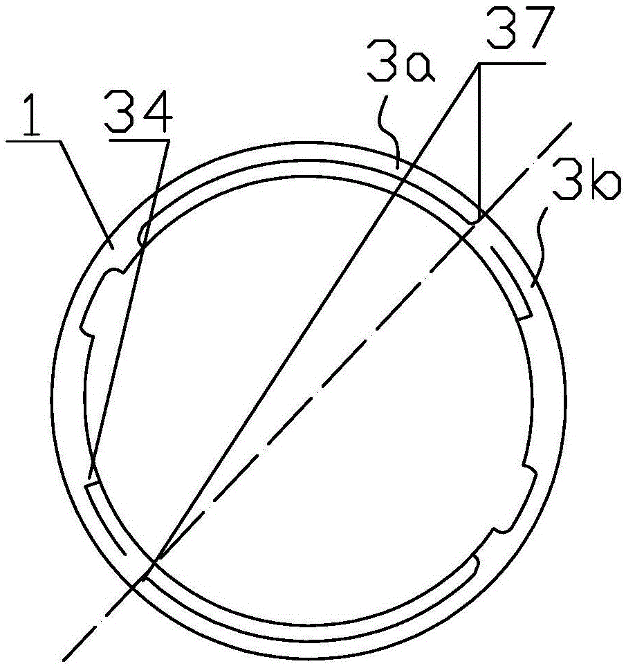
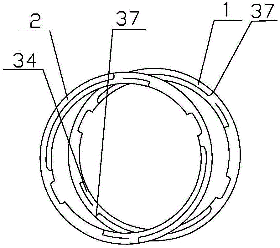
[0014] Please refer to image 3 One embodiment of the sealing assembly of the present invention includes a lower combination ring 1 and an upper combination ring 2, and the lower combination ring 1 and the upper combination ring 2 are installed in the same piston gas ring groove after overlapping. Please continue to refer figure 1 , the upper composite ring 2 and the lower composite ring 1 have the same structure, both including a C-type main ring 3a and a C-type secondary ring 3b, the C-type secondary ring 3b and the C-type main ring 3a have the same structure, figure 1 The C-shaped auxiliary ring 3b shown on the right is obtained by rotating the C-shaped main ring 3a on the left by 180 degrees.

[0015] The C-shaped main ring 3a and the C-shaped auxiliary ring 3b include a semi-circular body 31 and ...


PUM


Abstract

The invention provides a circular seal assembly which comprises a lower combination ring and an upper combination ring. The lower combination ring and the upper combination ring are staggered and overlapped and then mounted in the same piston gas ring groove, the structure of the upper combination ring is as same as that of the lower combination ring, a main C-shaped ring and an auxiliary C-shaped ring are mutually spliced to form each combination ring and respectively comprise a semicircular ring body and a first containing port matched with an elastic part, each first containing port opposite to the corresponding elastic part is formed in the inner wall of the other end of the elastic part with a quarter arc structure, each elastic part is connected with one end of the corresponding semicircular ring body, each semicircular ring body is further provided with a positioning groove and a positioning pin, a ring port is formed in the joint of the two semicircular ring bodies when each auxiliary C-shaped ring and the corresponding main C-shaped ring are spliced, the ring ports of the upper combination ring and the lower combination ring are mutually staggered when the upper combination ring and the lower combination ring are overlapped, and each positioning pin is bent upwards and clamped into the corresponding positioning groove. The circular seal assembly is fine in tightness and high in radial and axial positioning function, so that the power of a fuel engine is improved, and fuel consumption and emission pollution are reduced.

Description

technical field [0001] The invention relates to the technical field of power machinery piston sealing, in particular to a circular sealing piston ring assembly. Background technique [0002] The piston ring is the core component inside the fuel engine. It completes the sealing of the fuel gas together with the cylinder, piston, and cylinder wall, and plays the role of sealing, lubrication, heat conduction and positioning. There are many deficiencies in the currently used piston rings: one is poor sealing. In order to ensure the normal operation of the piston ring in the cylinder and the piston ring groove, the piston ring needs to leave a necessary opening gap, which makes the gas in the cylinder leak through it to the crankshaft box, resulting in a decrease in fuel engine power, increased fuel consumption, and serious emission pollution; second, the positioning effect is not strong, and the forces acting on the piston ring include gas pressure, the ring's own elasticity, th...

Claims


Application Information

Patent Timeline
Patent Type & Authority Patents(China)
IPC IPC(8): F02F5/00
Inventor 张枫陈国华沈媛梁蕃焕周双彧
Owner 广州世喜科技有限公司
Why Eureka
Try Eureka