
Data transmission method and system of USB camera

A technology of a data transmission system and a data transmission method, which is applied in the field of data transmission, can solve the problems of increasing equipment cost, not supporting multi-channel direct connection, USB signal cannot maintain normal transmission of USB signal, etc., and achieve the effect of reducing equipment cost

Active Publication Date: 2014-01-29
SHENZHEN LONTIUM SEMICON TECH CO LTD
View PDF5 Cites 5 Cited by
  • Summary
  • Abstract
  • Description
  • Claims
  • Application Information

AI Technical Summary

Problems solved by technology

More than 5 meters may not be able to maintain the normal transmission of the USB signal due to the attenuation of the USB signal
In order to maintain the normal transmission of USB signals, the distance between the main control device and the USB camera should not exceed 5 meters, which limits the application of the USB camera in the field of long-distance transmission applications such as in the field of video surveillance
[0003] In order to extend the transmission distance of the USB camera signal, the method of converting the USB signal into a network signal is adopted in the prior art, but this method requires a special power supply device to provide online power supply for the USB camera, which increases the cost of the device
And since the usual master control device generally has only one network interface, this method does not support multiple direct connections
Moreover, in some application fields such as car monitoring applications and scientific research image processing, the opencv software does not support network signals, so the method of converting USB signals into network signals has certain limitations.
[0004] In addition, the method of extending the transmission distance of USB signals by converting USB signals into network signals requires high bandwidth
If the network bandwidth of 100M is used to transmit high-definition image data, the transmission quality may be affected due to the small bandwidth

Method used


Image

  • Data transmission method and system of USB camera
  • Data transmission method and system of USB camera
  • Data transmission method and system of USB camera

Examples


Embodiment Construction

[0037] In order to make the purpose, technical solutions and advantages of the embodiments of the present invention clearer, the technical solutions in the embodiments of the present invention will be clearly and completely described below in conjunction with the drawings in the embodiments of the present invention. Obviously, the described embodiments It is a part of embodiments of the present invention, but not all embodiments. Based on the embodiments of the present invention, all other embodiments obtained by persons of ordinary skill in the art without making creative efforts belong to the protection scope of the present invention.

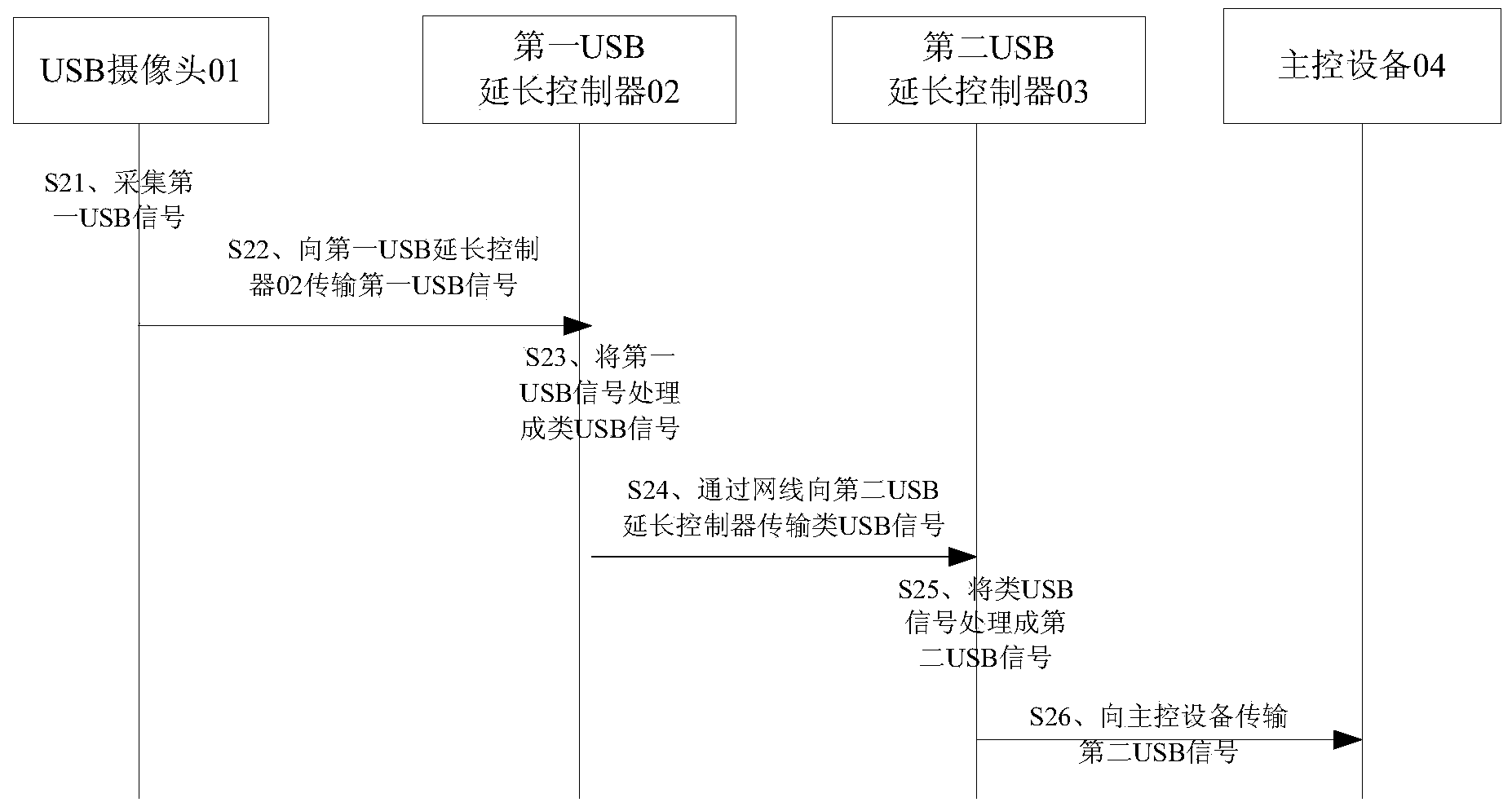
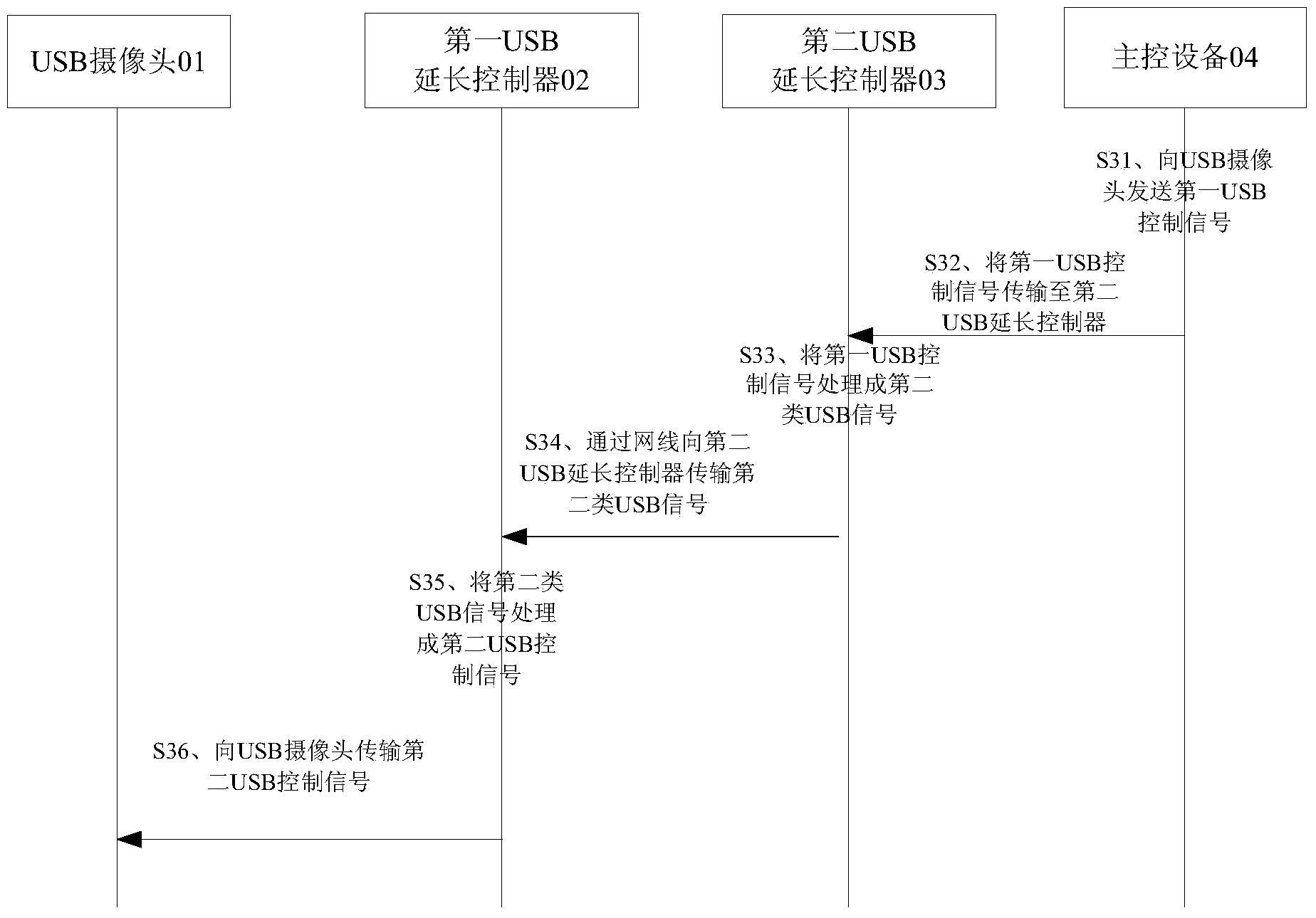
[0038] see figure 1 , figure 1 It is a schematic structural diagram of a USB camera data transmission system according to an embodiment of the present invention. Such as figure 1 As shown, the data transmission system includes a USB camera 01 , a first USB extension controller 02 , a second USB extension controller 03 and a master device 0...


PUM


Abstract

The invention provides a data transmission method and system of a USB camera. The data transmission system of the USB camera comprises the USB camera, a first USB extension controller, a second USB extension controller and a main control device, wherein the first USB extension controller is used for processing first USB signals collected by the USB camera to form USB-like signals, and the second USB extension controller is used for processing the USB-like signals to form second USB signals. Due to the fact that the USB-like signals are reinforced signals, the USB-like signals can be transmitted to a place which is 100 meters away through a network cable, and normal transmission of the USB-like signals cannot be influenced. Due to the fact that a USB connecting line supports on-line power supply, a special on-line power supply device is not needed, and the equipment cost is reduced compared with the cost of a USB signal extension scheme in the prior art.

Description

technical field [0001] The invention relates to the technical field of data transmission, and more specifically, to a data transmission method and system of a USB camera. Background technique [0002] Currently, USB cameras are widely used in the field of personal video. The interface of the USB camera is generally a USB2.0 interface. Since the USB signal strength is seriously attenuated during the transmission process, the distance for USB2.0 to transmit the USB camera signal is generally less than 5 meters. Due to the attenuation of the USB signal, the normal transmission of the USB signal may not be maintained beyond 5 meters. In order to be able to maintain the normal transmission of USB signals, the distance between the main control device and the USB camera is required to be no more than 5 meters, which limits the application of the USB camera in the field of long-distance transmission applications such as in the field of video surveillance. [0003] In order to prol...

Claims


Application Information

Patent Timeline
IPC IPC(8): H04L12/879H04L29/08H04L49/901
Inventor 张俊
Owner SHENZHEN LONTIUM SEMICON TECH CO LTD
Learn More