Heart rate measurement method and device

A measurement method and a technology of a measurement device, which are applied in diagnostic recording/measurement, medical science, sensors, etc., can solve problems such as difficult to measure heart rate with one hand, inconvenient use, etc., and achieve the effect of improving application range and adaptability

Inactive Publication Date: 2014-02-05
ADSMART TECH
View PDF5 Cites 19 Cited by
  • Summary
  • Abstract
  • Description
  • Claims
  • Application Information

AI Technical Summary

Problems solved by technology

[0003] Both of the above two measurement methods have certain defects. The former can only be used in places with thin skin (such as fingers and earlobes) due to the fixed infrared output power, which belongs to static measurement. Side signal, it is difficult to measure heart rate with one hand, or need to touch the skin and wear the measurement device on the chest, which is very inconvenient to use

Method used


Image

  • Heart rate measurement method and device
  • Heart rate measurement method and device
  • Heart rate measurement method and device

Examples


Embodiment 1

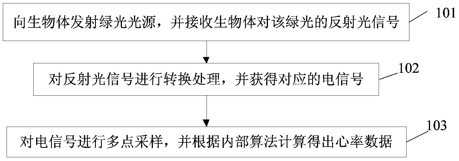
[0027] see figure 1 , the present embodiment provides a heart rate measurement method, which is applicable to the dynamic and static measurement of the heart rate of a living body, and its main steps and working principles include:

[0028] Step 101: Emitting a green light source to the organism, and receiving a reflected light signal of the green light from the organism.

[0029] In this embodiment, a pure green light source is emitted to the living body, and the light penetrates the skin to come to fat, muscle, and fine blood vessels, and the blood flow drives the flow of oxygen-carrying red blood cells and deoxygenated red blood cells; The cells have a reflective effect and a transmissive effect on the other liquid components of the blood, receiving the reflected light signal of the green light source.

[0030] As an example of this embodiment, after emitting a green light source to the living body and receiving the reflected light signal of the green light from the living...

Embodiment 2

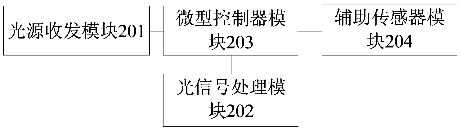
[0041] see figure 2 , the present embodiment provides a heart rate measurement device, which is suitable for dynamic and static measurement of the heart rate of a living body, and the measurement device includes: a light source transceiver module 201, an optical signal processing module 202, a microcontroller module 203, and an auxiliary sensor module 204 .

[0042] The working principle and connection structure of each part of the device are as follows:

[0043] The light source transceiver module 201 is electrically connected with the optical signal processing module 202 and the microcontroller module 203 respectively, and is used for emitting a green light source to the living body and receiving the green light emission signal.

[0044] In this embodiment, the light source transceiver module 201 may include, but is not limited to: a photosensitive element module and at least one light emitting diode. The light-emitting diode emits a pure green light source to the living bo...


PUM


Abstract

The invention relates to the field of electronic measurement, and discloses a heart rate measurement method and a heart rate measurement device. The method comprises the following steps that a green light source is sent to a living body, in addition, reflecting light signals of the living body on green light are received; the reflecting light signals are subjected to conversion processing, and in addition, corresponding electric signals are obtained; the electric signals are subjected to multi-point sampling, and in addition, the heart rate data is obtained through being calculated according to an internal algorithm, wherein the internal algorithm is selected through analyzing auxiliary signals provided by an auxiliary sensor module by a miniature controller. The technical scheme provided by the invention is adopted, the heart rate can be measured both statically and dynamically, and in addition, one or several auxiliary sensors can be selected and matched for improving the dynamic heart rate output accuracy. In addition, besides the dynamic measurement improvement, the method and the device also have the advantages of self adaptability to the organism measured parts and different skin colors and the like.

Description

technical field [0001] The invention relates to the technical field of electronic measurement, in particular to a heart rate measurement method and device. Background technique [0002] In the existing biological heart rate measurement, infrared transmission or reflection technology is used to transmit infrared light to the skin of the living body, and after the red blood cells and other liquids of the living body are transmitted and reflected, the received signal is amplified and transformed into a series of The heart rate pulse signal; the second is the ECG technology, which uses the principle that there will be a biopotential difference between the two ends of the living body from the heart, and obtains a potential difference through the conductor contact at the two ends of the living body heart, and then obtains a heart rate pulse through the comparison amplifier circuit. signal to obtain the heart rate data of the organism. [0003] Both of the above two measurement me...

Claims


Application Information

Patent Timeline
Patent Type & Authority Applications(China)
IPC IPC(8): A61B5/0245
Inventor 丁杨苏振柳钱国重
Owner ADSMART TECH
Why Eureka
Try Eureka