
Filtering device of sewage treatment vehicle

A filter device and sewage treatment technology, applied in the direction of filtration and separation, fixed filter elements, chemical instruments and methods, etc., can solve the problems of incomplete methods, large layout space, cumbersome process, etc., and achieve convenient and reliable operation and save installation Space, the effect of increasing the filter area

Active Publication Date: 2015-05-27
WUHAN UNIV OF TECH
View PDF8 Cites 0 Cited by
  • Summary
  • Abstract
  • Description
  • Claims
  • Application Information

AI Technical Summary

Problems solved by technology

Existing sewage treatment plants transport scattered domestic sewage over long distances for centralized treatment. This treatment method is not only ineffective, but also consumes a lot of transportation costs, and the treatment workshop cannot realize mobile operations.
[0003] In order to solve this problem, different types of sewage treatment vehicles have emerged. For example, the utility model of the authorized announcement number CN 201473395 U discloses a kind of septic tank sewage treatment equipment, which uses the principles of filter screen interception, vacuum suction and centrifugal sedimentation Sewage separation, the method of vacuum suction separation of solid and liquid is not thorough, the separated objects will still contain more water, the energy consumed by centrifugal sedimentation is high, and it is not easy to process a large amount of sewage at the same time; another example is the authorized announcement number CN 102515415 A The invention patent of the company discloses a sewage treatment vehicle, which uses high-efficiency flow-away biotechnology to treat sewage. Biological treatment of sewage can achieve good environmental effects, but the process takes a long time and cannot meet the current pace of rapid operation; another example is the authorization announcement The invention patent of No. CN102874954 A discloses a sewage treatment system, which adopts multi-stage separation technology, including centrifugal separation, mechanical extrusion separation and adsorption separation of activated carbon, etc., and the layout space required by the hydraulic mechanical extrusion mechanism is relatively large. Increased the difficulty of layout, activated carbon adsorption takes a long time
The above-mentioned system has the disadvantages of complex structure, low efficiency, cumbersome process, etc.

Method used


Image

  • Filtering device of sewage treatment vehicle
  • Filtering device of sewage treatment vehicle
  • Filtering device of sewage treatment vehicle

Examples


Embodiment 1

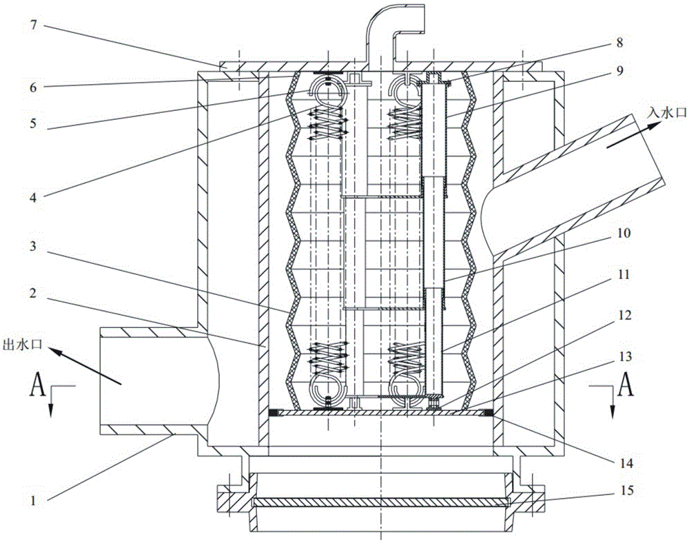
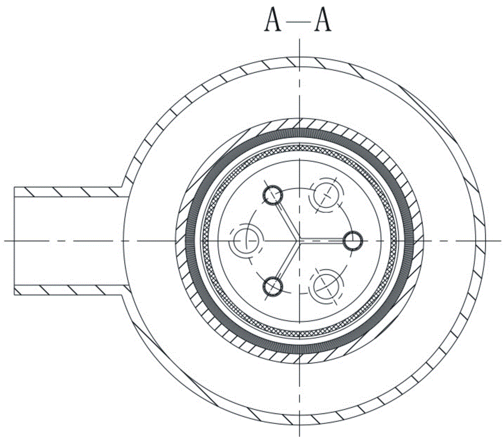
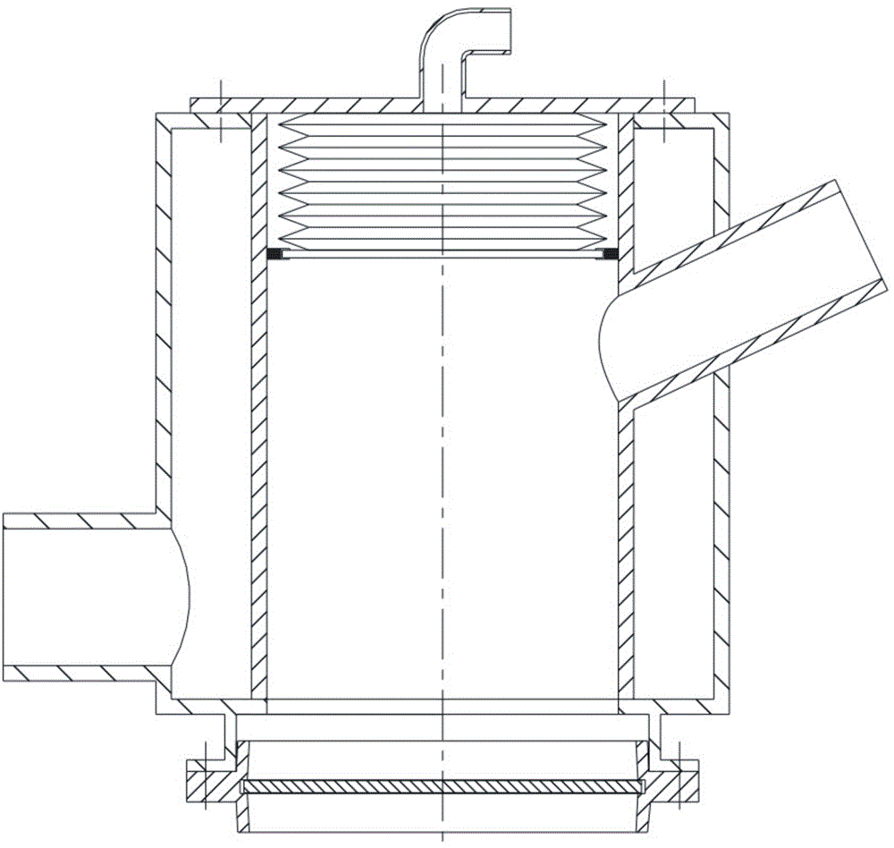
[0027] Such as Figure 1 to 9 As shown, it is a schematic structural diagram of an embodiment provided by the present invention. It can be seen from the figure that it includes a filter cartridge 1, which is open at both ends, and a filter screen 2 and a filter screen 2 are provided in the filter cartridge 1 The two ends of the airbag are connected with the two ends of the filter cartridge 1, and an airbag extrusion mechanism is provided in the filter screen 2. The airbag extrusion mechanism includes an airbag 3, an airbag cover 7, and an airbag bottom plate 13. One end of the airbag 3 and the airbag cover 7 is connected, the airbag cover 7 is fixedly connected with one end of the filter cartridge 1, and the other end of the airbag 3 is connected with the airbag bottom plate 13. A wiper is installed on the outer peripheral edge of the airbag bottom plate 13, and the wiper is connected to the filter cartridge The inner wall of 1 is in contact with each other, so that the outer p...

Embodiment 2

[0034] Such as Picture 10 As shown, it is a schematic structural diagram of another embodiment of the guide mechanism and the spring provided by the present invention. The structure of this embodiment is basically the same as that of the first embodiment. The difference is that the airbag cover 7 and the airbag bottom plate 13 A set of guide rods and three tension springs 5 ​​are connected in between, of which there is only one set of guide rods, consisting of three upper, middle and lower guide rods 9, 10 and 11, and the three springs 5 ​​are evenly arranged around the guide rods. In this embodiment, the spring base and the upper and lower bases of the guide rod are eliminated, and they are directly processed on the airbag cover 7 and the airbag bottom plate 13, wherein the upper guide rod 9 in the guide rod is fixedly connected to the airbag cover 7, and the lower part of the guide rod The guide rod 11 is fixedly connected to the airbag bottom plate 13. This embodiment has s...


PUM


Abstract

The invention discloses a filtering device of a sewage treatment vehicle. The filtering device comprises a filter cylinder, wherein the filter cylinder is internally provided with a filter screen; the two ends of the filter screen are connected with the two ends of the filter cylinder, and the filter screen is internally provided with a gasbag extruding mechanism; the gasbag extruding mechanism comprises a gasbag, a gasbag cover plate and a gasbag bottom plate; one end of the gasbag is connected with the gasbag cover plate which is fixedly connected with one end of the filter cylinder, and the other end of the gasbag is connected with the gasbag bottom plate; the periphery of the gasbag bottom plate is in slide fit with the inner wall of the filter screen, at least one group of springs are arranged on a position which is positioned between the gasbag cover plate and the gasbag bottom plate and is arranged in the gasbag, and the other end of the filter cylinder is connected with a knife valve; the filter screen is provided with a water inlet which is communicated with the filter screen, the filter cylinder is provided with a water outlet which is communicated with a cavity formed between the filter cylinder and the filter screen, and the gasbag cover plate is provided with inlet and exhaust holes. The filtering device provided by the invention has the advantages that the structure is simple, the operation is convenient, the efficiency is high, and stretching and contracting processes of the gasbag are finished in the filter screen, so that the space occupation is small.

Description

Technical field [0001] The invention relates to a filter device of a sewage treatment vehicle. Background technique [0002] As the water pollution problem continues to aggravate and the requirements for environmental quality become increasingly stringent, the treatment and recycling of sewage has become an increasingly important part of environmental and resource protection. Existing sewage treatment plants transport scattered domestic sewage through long-distance transportation and then centralized treatment. This treatment method is not only ineffective, but also consumes a lot of transportation costs. The treatment workshop cannot achieve mobile operations. [0003] In order to solve this problem, different types of sewage treatment vehicles have emerged. For example, the utility model of authorized announcement number CN 201473395 U discloses a septic tank sewage treatment equipment, which is intercepted by a filter, vacuum suction and centrifugal sedimentation. For sewage se...

Claims


Application Information

Patent Timeline
Patent Type & Authority Patents(China)
IPC IPC(8): B01D29/35B01D29/64B01D29/82B01D29/84
Inventor 华林李晚霞何耀华徐杨坤杨灿
Owner WUHAN UNIV OF TECH
Learn More