A method and device for measuring optical delay
A technology of optical delay and measurement method, which is applied in the field of high-precision time delay measurement, and can solve the problems of inability to achieve delay control, millimeter-level length error, etc.
- Summary
- Abstract
- Description
- Claims
- Application Information
AI Technical Summary
Problems solved by technology
Method used
Image
Examples
Embodiment 1
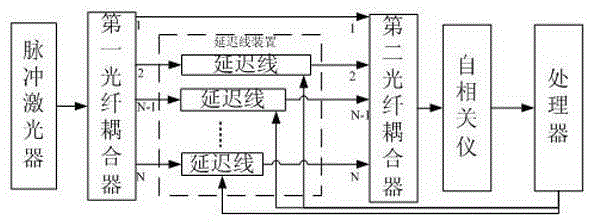
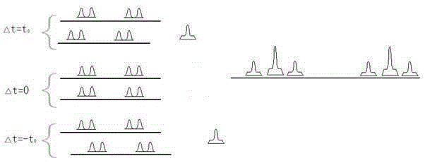
[0058] Embodiment 1: The device includes a delay line, the first fiber coupler is a 1*2 fiber coupler, and the second fiber coupler is a 2*1 fiber coupler. Such as figure 2 As shown, the input light of the pulsed laser is divided into two paths by the first fiber coupler, one of which is connected to the fiber delay line for delay control, and then connected by the second coupler to combine the two paths of optical pulses with time difference into one path . If the delay line delay is t 0 , then the distance between the undelayed laser beam signal and the laser beam signal passing through the delay line is t 0 . Similarly, if it is necessary to delay the laser beam pulse by N times, select 1*N first fiber couplers, N*1 second fiber couplers and N−1 delay lines.
[0059] The delayed laser beam pulse is input to the autocorrelator, and the optical path of the autocorrelator is adjusted until the autocorrelation signal appears. Since the rotating arm of the autocorrelator c...
Embodiment 2
[0062] Embodiment 2: The device includes 7 delay lines, the first fiber coupler is a 1*8 fiber coupler, and the second fiber coupler is an 8*1 fiber coupler. The input light of the pulsed laser is divided into 8 paths on average through the first fiber coupler, the first path is connected to the first input port of the second fiber coupler, the second path of the first fiber coupler to the eighth path of the second fiber coupler are respectively Connect the delay line for delay control, and then use the 8*1 fiber coupler to combine the 8 optical pulses with time difference into one. If the delay line delay is t 0 , then the distance between the undelayed laser beam signal and the laser beam signal passing through the delay line is t 0 、2t 0 、3t 0 、4t 0 、5t 0 、6t 0 、7t 0 .
[0063] The laser beam pulses passing through the second fiber coupler are input to the autocorrelator, and the optical path of the autocorrelator is adjusted until an autocorrelation signal appears....
PUM
 Abstract
Description
Claims
Application Information
 - R&D
- Intellectual Property
- Life Sciences
- Materials
- Tech Scout
- Unparalleled Data Quality
- Higher Quality Content
- 60% Fewer Hallucinations
Browse by: Latest US Patents, China's latest patents, Technical Efficacy Thesaurus, Application Domain, Technology Topic, Popular Technical Reports.
© 2025 PatSnap. All rights reserved.Legal|Privacy policy|Modern Slavery Act Transparency Statement|Sitemap|About US| Contact US: help@patsnap.com


