
A multifunctional load simulation test bench

A technology of load simulation and test bench, which is applied in the testing of machine/structural components, measuring devices, instruments, etc., which can solve the problem of failure to consider the comfort of installation, disassembly, and replacement of test personnel, the stress of the main body of the test bench, and the inability to Accurately realize the load dynamic simulation and other problems, achieve the effect of convenient processing, production and disassembly, avoid unbalanced radial force, and obvious cost advantages

Inactive Publication Date: 2015-11-04
BEIHANG UNIV
View PDF6 Cites 0 Cited by
  • Summary
  • Abstract
  • Description
  • Claims
  • Application Information

AI Technical Summary

Problems solved by technology

[0004] The currently known load simulators have complex structures, large volumes or limited carrying capacity, and cannot accurately realize the dynamic simulation of the load, let alone simulate the inertia of the load end
Most of the existing load simulation devices do not consider the simplicity and convenience of installation, disassembly, replacement and operation and the comfort of the test personnel; at the same time, the existing load simulation devices do not consider the stress of the main body of the test bench and how to effectively The problem of reducing the radial unbalanced force can be minimized, which cannot be ignored in the case of high power and large moment loading; in addition, the existing load simulators have little consideration for the simulation of the inertia of the rudder surface, and most of them can only simulate the fixed inertia It is not even possible to simulate the inertia

Method used


Image

  • A multifunctional load simulation test bench
  • A multifunctional load simulation test bench
  • A multifunctional load simulation test bench

Examples


Embodiment Construction

[0052] The technical solutions of the present invention will be further described below in conjunction with the accompanying drawings and embodiments.

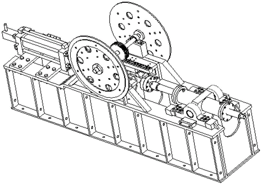
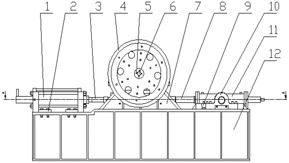
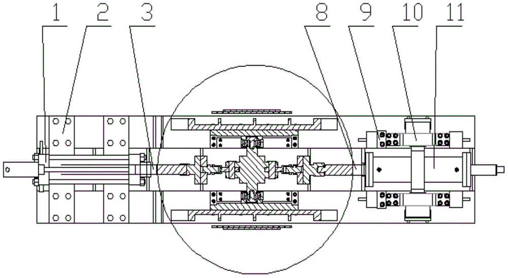
[0053] refer to figure 1 , the present invention is a multifunctional load simulation test bench, which includes a base 12, a loading steering gear 11, a loading steering gear fixing ear seat 10, a loading steering gear front and rear position adjustment wedge 9, a loading steering gear left and right position adjustment block 33, Pull pressure sensors 22, 14, connecting flanges 21, 13, output shaft 8 of the loading steering gear, intermediate inertia block 18, earring shaft 16 of the steering gear under test, 1 steering gear under test, mounting plate 2 of the steering gear under test, rack 31. Gear 27, gear shaft 28, gear shaft support 29, rolling bearing 25, intermediate support 7, inertia disk 4, anti-rotation "cross" frame 5, threaded plug 6 and anti-lateral force guide wheel 26, adapter 15,23, pins 17,19, guide wheel ba...


PUM


Abstract

A multifunctional load stimulation test stand comprises a base, a load steering engine, a load steering engine fixing lug base, a load steering engine front-and-back position adjusting wedge block, a load steering engine left-and-right position adjusting block, a pull pressure sensor, a connecting flange, a load steering lug ring shaft, a middle inertia block, a measured steering engine output shaft, a measured steering engine, a measured steering engine installing plate, a rack, a gear, a gear shaft, a gear shaft support, a rolling bearing, a middle bracket, an inertia disc, an anti-rotation cross, a threaded end cap, a lateral force prevention guide wheel, a load steering engine output shaft, an adaptor, a dowel, a guide wheel baffle, a gear shaft support bearing, a load steering engine left-and-right position adjusting screw and a measured steering engine lug ring shaft. By the adoption of the test stand, the performance of the measured steering engine is accurately and reliably tested through the simplest structure and operation most convenient to conduct and at lowest using cost. The multifunctional load stimulation test stand has the advantages of being convenient to demount and mount and high in universality of an installing conversion structure, and can also be suitable for other equipment needing loading.

Description

technical field [0001] The invention relates to a multifunctional load simulation test bench, which can test the technical performance index of the tested steering gear by simulating the load and load end inertia of the tested steering gear, and is especially suitable for aerospace ground semi-physical simulation The simulated test of the load on the aircraft rudder drive steering gear and the inertia of the load end. The utility model belongs to the technical field of aerospace simulation test equipment. Background technique [0002] The multifunctional load simulation test bench is an important equipment for the ground half-physical simulation laboratory to dynamically simulate the load and inertia of the load end of the rudder surface driven steering gear of aircraft such as missiles in flight. It is an important part of the large-circuit half-physical simulation system of the aircraft. . With the development of science and technology, the requirements for the maneuvera...

Claims


Application Information

Patent Timeline
Patent Type & Authority Patents(China)
IPC IPC(8): G01M99/00
Inventor 付永领范殿梁祁晓野张健王利剑张朋刘浩
Owner BEIHANG UNIV
Learn More