
Thermoelectricity boiler drum liquid level control method

A boiler drum and liquid level control technology, applied in adaptive control, general control system, control/regulation system, etc., can solve the problems of long lag time, large inertia, and reduced water volume in the drum, and achieve high efficiency and stability production effect

Active Publication Date: 2014-02-05
WISDRI ENG & RES INC LTD
View PDF4 Cites 22 Cited by
  • Summary
  • Abstract
  • Description
  • Claims
  • Application Information

AI Technical Summary

Problems solved by technology

[0002] The boiler drum liquid level control system is an important key process in the boiler production process. The stability of the boiler drum liquid level is crucial to maintaining boiler safety, improving boiler efficiency, and reducing production costs. During boiler operation, the steam drum liquid level There are many factors affecting the stability, the main ones are the feed water flow and steam flow. When the feed water flow increases, because the temperature of the feed water is relatively low, it absorbs heat from the original saturated water and reduces the drum water volume. Therefore, The water level of the steam drum does not rise immediately at the beginning, but shows an initial inertia stage; when the steam load increases, from the perspective of material balance, the steam volume is greater than the feed water volume, and the water level should drop, but in practice, a sudden increase in the steam load will cause As a result, the pressure of the steam drum decreases, the volume of steam in the steam-water mixture increases rapidly, and the water level rises rapidly, that is, the "false water level" phenomenon; The physical characteristics will change accordingly, which will cause the problem of model mismatch; in short, the boiler drum liquid level system is a system with large inertia, long lag time, and nonlinear time-varying

Method used


Image

  • Thermoelectricity boiler drum liquid level control method
  • Thermoelectricity boiler drum liquid level control method
  • Thermoelectricity boiler drum liquid level control method

Examples


Embodiment Construction

[0029] The specific embodiments of the present invention will be further described in detail below in conjunction with the accompanying drawings.

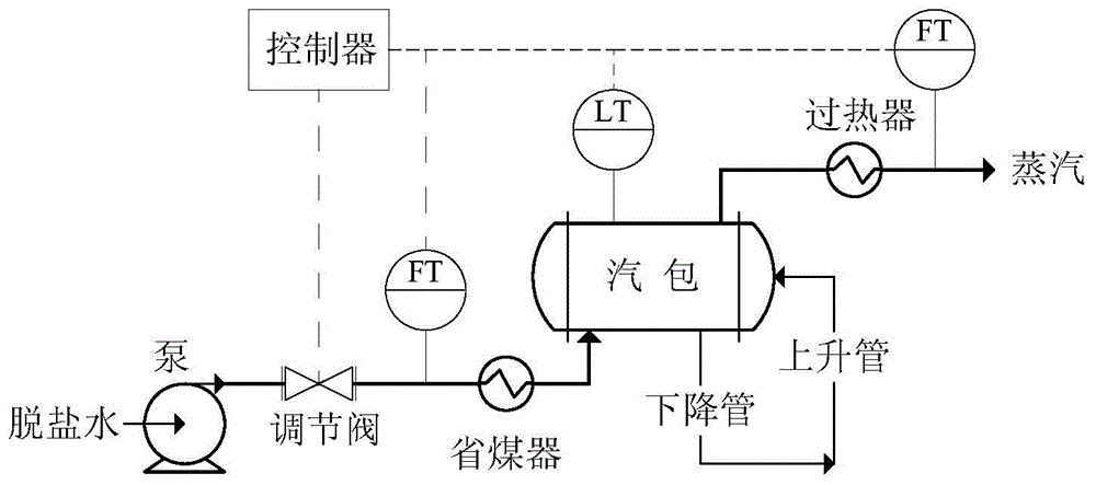
[0030] The steam drum liquid level control method of the thermoelectric boiler involved in the present invention takes three variables of steam drum liquid level, feed water flow rate and steam flow rate as processing objects, the control system adopts a feedforward + cascade structure as a whole, and the main regulator adopts a steam drum The liquid level is a conventional PID regulator that detects and controls variables. The deviation between the set value SP of the steam drum liquid level and the actual measured value LT is calculated by the PID regulator, and the output is the set value of the feed water flow; The measured value is used as the feed-forward control quantity; the sub-regulator adopts a single-neuron adaptive PSD regulator with the feedwater flow as the detection and control variable.

[0031] figure 1 Among the...


PUM


Abstract

The invention relates to a thermoelectricity boiler drum liquid level control method, three variables of a drum liquid level, feed water flow and steam flow are taken as processing objects, a feedforward and cascade stage structure is wholly adopted for a control system, a conventional PID adjuster with the drum liquid level as a detecting and controlling variable is adopted for a main adjustor, and the deviation between the set value SP of the drum liquid level and the actual measured value LT is calculated through the PID adjuster and output as the set value of the feed water flow; the measured value of the drum externally supplied steam flow is taken as a feedforward control variable; a single-neuron self-adaptive PSD adjuster with the feed water flow as a detecting and controlling variable is adopted for an auxiliary adjustor. Through the technical scheme, aiming at complex conditions of boiler drum operation, advanced, reliable and practical calculation is adopted to achieve self-adaptive optimum control over the boiler drum liquid level and ensure efficient and stable production of a boiler.

Description

technical field [0001] The invention relates to a boiler liquid level control method, in particular to a thermoelectric boiler steam drum liquid level control method. Background technique [0002] The boiler drum liquid level control system is an important key process in the boiler production process. The stability of the boiler drum liquid level is crucial to maintaining boiler safety, improving boiler efficiency, and reducing production costs. During boiler operation, the steam drum liquid level There are many factors affecting the stability, the main ones are the feed water flow and steam flow. When the feed water flow increases, because the temperature of the feed water is relatively low, it absorbs heat from the original saturated water and reduces the drum water volume. Therefore, The water level of the steam drum does not rise immediately at the beginning, but shows an initial inertia stage; when the steam load increases, from the perspective of material balance, the ...

Claims


Application Information

Patent Timeline
IPC IPC(8): G05B13/00
Inventor 常杰锋
Owner WISDRI ENG & RES INC LTD
Learn More