Method for producing aromatic hydrocarbons

a technology of aromatic hydrocarbons and hydrocarbons, which is applied in the direction of hydrocarbon oil treatment products, catalyst regeneration/reactivation, physical/chemical process catalysts, etc., can solve the problems of insufficient amount of coke adhered to the reforming catalyst in the fluidized bed reactor to allow the combustion of coke, and the method used for supplying the heat required by the reaction and the technique used for controlling the associated temperature are often problematic issues, so as to achieve efficient and stable

Inactive Publication Date: 2012-01-19
CHIYODA CORP +1
View PDF14 Cites 10 Cited by
  • Summary
  • Abstract
  • Description
  • Claims
  • Application Information

AI Technical Summary

Benefits of technology

[0022]The method for producing aromatic hydrocarbons according to the present invention is a method for producing aromatic hydrocarbons using LCO produced from an FCC apparatus, naphtha and straight-run gas oil as the feedstock, which enables the aromatic hydrocarbons to be produced in an efficient and stable manner.

Problems solved by technology

Because the reforming reaction is usually an endothermic reaction, the method used for supplying the heat required by the reaction and the technique used for controlling the associated temperature are often problematic issues.
Further, the generation of coke that accompanies the reaction operation, which is an issue even when a light naphtha is used as the feedstock, becomes far more marked when a heavy naphtha or particularly a light cycle oil (hereinafter abbreviated as LCO) or gas oil is used as the feedstock, and the frequency with which the reforming catalyst must be regenerated also increases markedly.
However, the amount of coke adhered to the reforming catalyst in the fluidized bed reactor is insufficient to allow the combustion of the coke inside the regenerator to generate the necessary heat for the reforming reaction (endothermic reaction) of the feedstock inside the fluidized bed reactor.
These accumulated impurities tend to cause localized heating, increasing the possibility of damage to the heating pipes, and therefore preheating the feedstock in this manner is not ideal.
Further, in those cases where rapid progression of the reforming reaction causes the temperature inside the fluidized bed reactor to decrease abruptly, the required heat cannot be supplied rapidly to the system.

Method used


Image

  • Method for producing aromatic hydrocarbons
  • Method for producing aromatic hydrocarbons

Examples


example 1

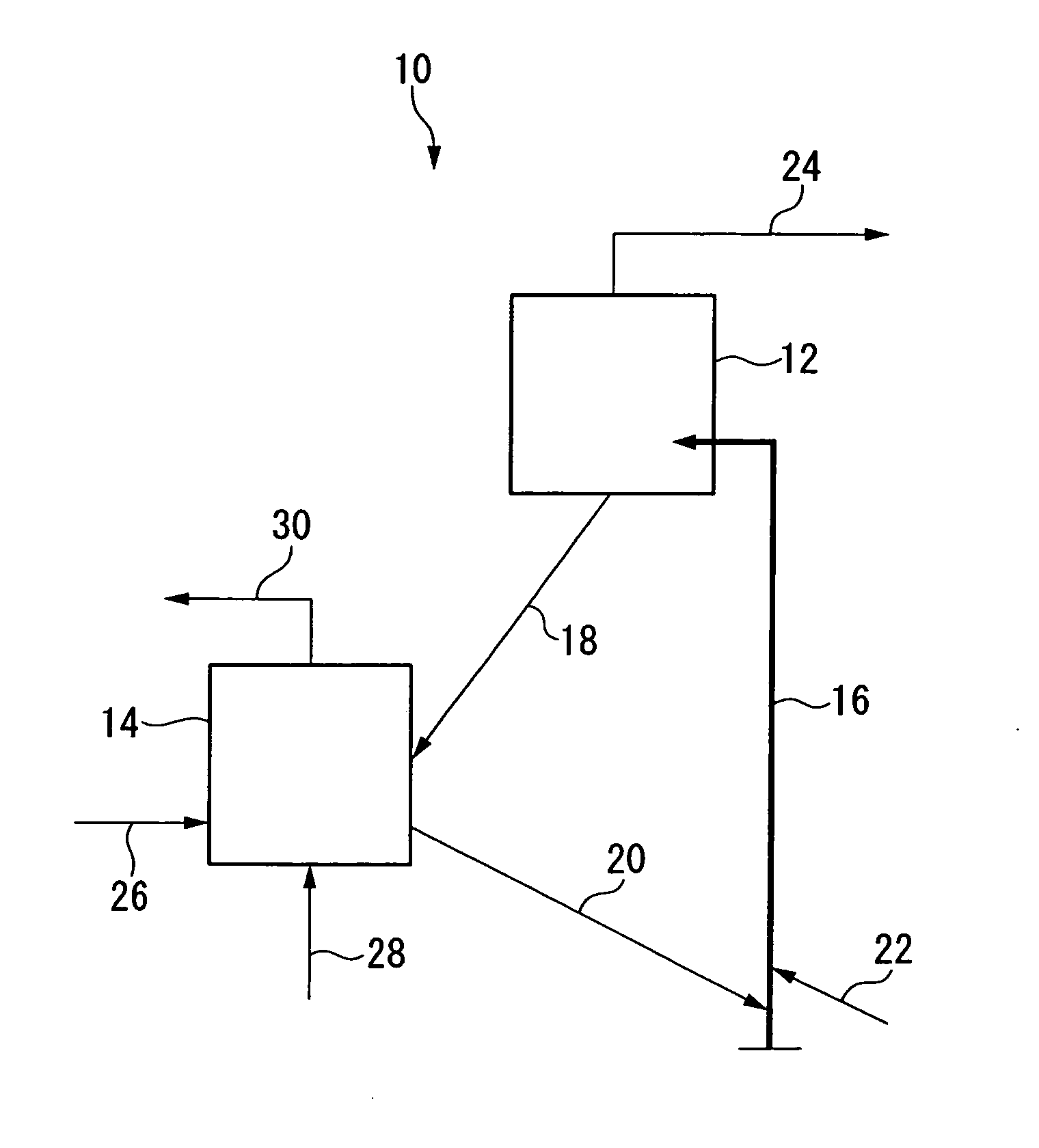
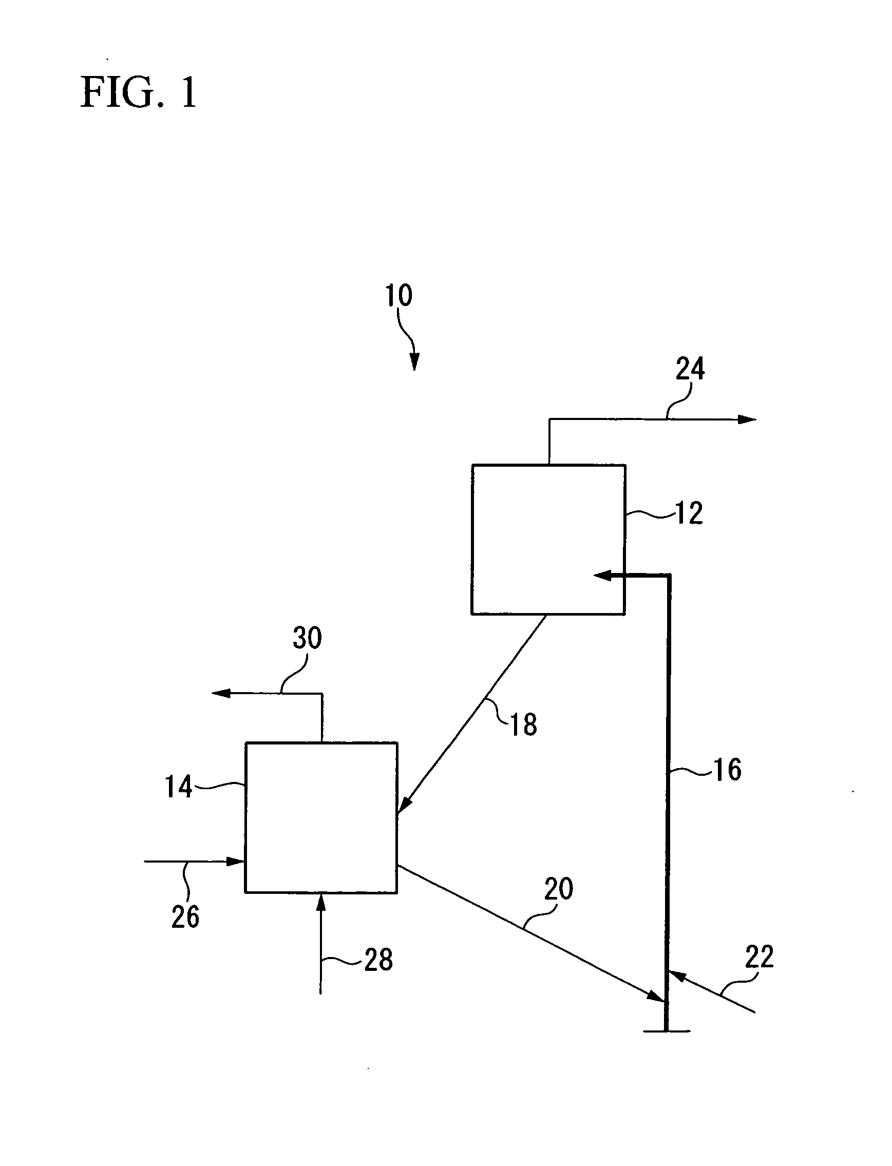
[0053]Using the fluid catalytic reforming apparatus 10 having the structure illustrated in FIG. 1, BTX production was performed under the operating conditions listed below, and the resulting data was used to calculate the production rate and the like for BTX.

Operating Conditions

[0054]Heating temperature of feedstock oil by preliminary heater (not shown in the FIGURE): 200° C.

[0055]Supply rate of the feedstock oil (vapor) to the catalyst riser 16: 1 ton / hour

[0056]Pressure inside the fluidized bed reactor 12: 0.3 MPaG

[0057]Reaction temperature inside the fluidized bed reactor 12: 560° C.

[0058]Contact time between the feedstock oil and the reforming catalyst inside the fluidized bed reactor 12: 18 seconds

[0059]Pressure inside the heating tank 14: 0.35 MPaG

[0060]Temperature inside the heating tank 14: 650° C.

[0061]Supply rate of the heating fuel to the heating tank 14: 0.025 tons / 1 ton of the feedstock oil

[0062]Supply rate of air to the heating tank 14: 0.80 tons / 1 ton of the feedstock ...


PUM

PropertyMeasurementUnit
temperatureaaaaaaaaaa
contact timeaaaaaaaaaa
temperatureaaaaaaaaaa

Abstract

A method for producing aromatic hydrocarbons in which at least one feedstock oil selected from the group consisting of LCO produced from an FCC apparatus, hydrotreated LCO, naphtha and straight-run gas oil is brought into contact with a reforming catalyst inside a fluidized bed reactor, wherein the method includes transporting a reforming catalyst that has been extracted from the fluidized bed reactor to a heating tank, heating the reforming catalyst in the heating tank to a temperature at least as high as the reaction temperature inside the fluidized bed reactor, and following heating, transporting the heated reforming catalyst to the fluidized bed reactor.

Description

TECHNICAL FIELD[0001]The present invention relates to a method for producing aromatic hydrocarbons. The method relates particularly to a method for producing aromatic hydrocarbons by a catalytic reforming reaction using a fluidized bed reactor.[0002]Priority is claimed on Japanese Patent Application No. 2009-078602, filed Mar. 27, 2009, the content of which is incorporated herein by reference.BACKGROUND ART[0003]Methods for producing aromatic hydrocarbons such as BTX (benzene, toluene, xylene and the like) by catalytic reforming of a light naphtha or heavy naphtha or the like obtained from a fluid catalytic cracking (hereinafter abbreviated as FCC) apparatus are well known. These production methods generally employ a system based on a fixed bed or moving bed that uses a granulated reforming catalyst.[0004]Because the reforming reaction is usually an endothermic reaction, the method used for supplying the heat required by the reaction and the technique used for controlling the associ...

Claims


Application Information

Patent Timeline
Patent Type & Authority Applications(United States)
IPC IPC(8): C10G35/04
CPCB01J29/048B01J29/405B01J29/87B01J29/90B01J37/0201B01J38/02C10G2400/30C07C2529/70C07C4/06C10G2300/1044C10G35/14C07C15/02Y02P20/584
Inventor MINAMI, HIDEKISUGI, YOSHISHIGEFUKUI, ATSUSHINAGUMO, ATSUROYANAGAWA, SHINICHIROHAYASAKA, KAZUAKI
Owner CHIYODA CORP
Why Eureka
Try Eureka