Communication system between FPGA (field programmable gate array) and computer
A communication system and computer technology, applied in the field of PCIe communication systems, can solve problems such as reducing system availability, increasing data transmission delay, and being difficult for users to use, and achieves the effect of accelerating research and development, improving efficiency, and saving time and manpower investment.
- Summary
- Abstract
- Description
- Claims
- Application Information
AI Technical Summary
Problems solved by technology
Method used
Image
Examples
specific Embodiment approach
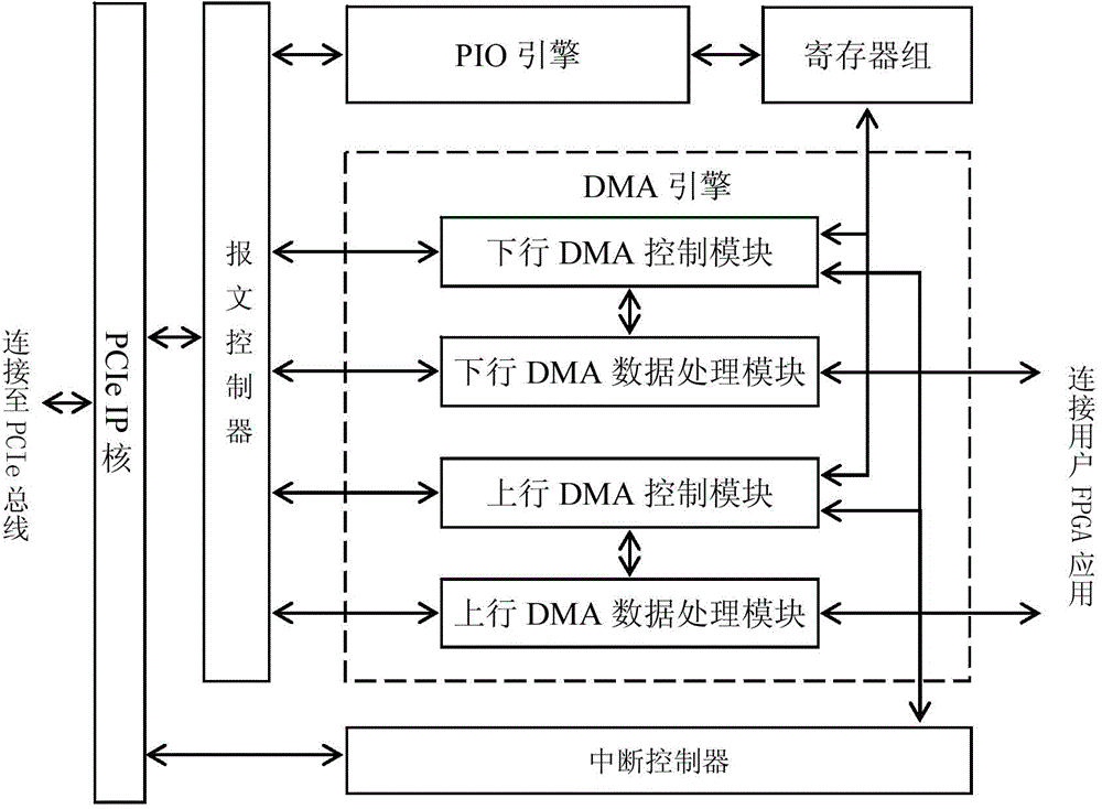
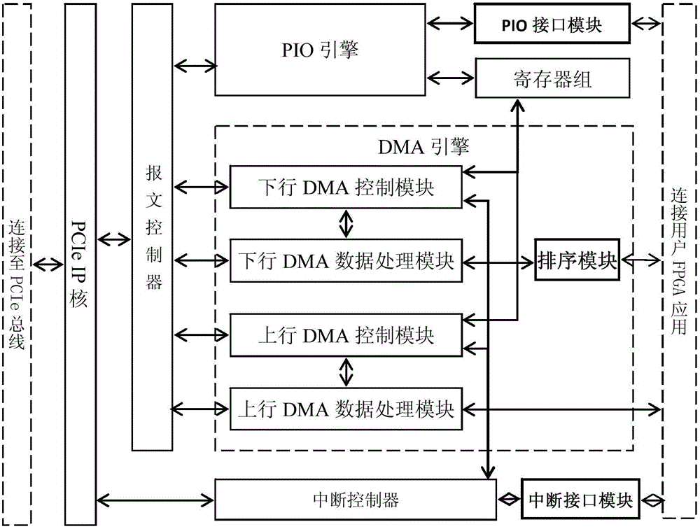
[0033] A communication system between FPGA and computer, including: DMA engine, PIO engine, register bank, message controller, interrupt controller and PCIe IP core (see figure 1 );in,
[0034] A. The DMA engine includes a downlink DMA control module, a downlink DMA data processing module, an uplink DMA control module, and an uplink DMA data processing module, wherein,
[0035]a) The downlink DMA control module is used to control the DMA from the computer to the FPGA direction (DMA in this direction is also called DMA read), and perform DMA on the DMA descriptor according to the DMA read start and DMA read descriptor address signals given by the register group operation, and then control the downlink DMA data processing module to perform DMA read operation through the DMA address and DMA length information in the DMA descriptor;
[0036] b) The downlink DMA data processing module is used to process the DMA (DMA in this direction is also called DMA read) data from the computer...
Embodiment 1
[0053] Embodiment 1: DMA data transmission from computer to FPGA direction
[0054] Assuming that the communication system between the FPGA and the computer described in the present invention has received a DMA request from the user software, the character string "1234" starting at memory location 0x45000004 needs to be transmitted to the user FPGA application through DMA data transmission. And the software has placed the DMA descriptor describing the above DMA operation in memory 0x43000000.
[0055] The PIO engine of the communication system between FPGA of the present invention and the computer will receive two PIO write requests, first write in the DMA read operation descriptor address register in the register group, the value of writing is 0x43000000; The first write to the DMA read start register in the register bank. At this time, the downlink DMA control module detects the start of DMA reading, so it makes a data request according to the value 0x43000000 in the DMA re...
Embodiment 2
[0059] Embodiment 2: DMA data transmission from FPGA to computer direction
[0060] Assuming that the communication system between the FPGA and the computer described in the present invention has received a DMA request from the user software, the character string "5678" in the FPGA needs to be transferred to the computer, specifically the 4 characters starting from DMA to memory 0x46000004 section. The software has placed the DMA descriptor describing the above DMA operation at 0x44000000 in memory.
[0061] The PIO engine of the communication system between FPGA of the present invention and the computer will receive twice PIO write request, first time writes DMA in the register group and writes the descriptor address register, and the value of writing is 0x44000000; Write to the DMA write start register in the register bank. At this time, the upstream DMA control module detects the start of DMA writing, so it makes a data request according to the value 0x44000000 in the DMA...
PUM
 Abstract
Description
Claims
Application Information
 - R&D
- Intellectual Property
- Life Sciences
- Materials
- Tech Scout
- Unparalleled Data Quality
- Higher Quality Content
- 60% Fewer Hallucinations
Browse by: Latest US Patents, China's latest patents, Technical Efficacy Thesaurus, Application Domain, Technology Topic, Popular Technical Reports.
© 2025 PatSnap. All rights reserved.Legal|Privacy policy|Modern Slavery Act Transparency Statement|Sitemap|About US| Contact US: help@patsnap.com


