Method for generating distributed synchronous pulses

A technology for synchronous pulses and generation methods, which is applied in the direction of synchronous devices, digital transmission systems, electrical components, etc., can solve the problems of synchronous ranging pulses, time synchronization of transceiver stations, etc., and achieves easy adjustment, short phase adjustment time, and simple and flexible methods Effect

Inactive Publication Date: 2014-02-05
BEIJING INSTITUTE OF TECHNOLOGYGY
View PDF3 Cites 3 Cited by
  • Summary
  • Abstract
  • Description
  • Claims
  • Application Information

AI Technical Summary

Problems solved by technology

However, one of the important technical issues is the time synchronization of transceiver stations. The radar needs to measure the target distance based on the time delay of the received echo relative to the transmitted signal. Therefore, strict time synchronization between transceiver stations must be maintained to generate synchronous ranging. pulse

Method used


Image

  • Method for generating distributed synchronous pulses
  • Method for generating distributed synchronous pulses
  • Method for generating distributed synchronous pulses

Examples


Embodiment

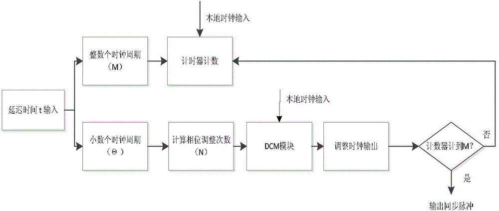
[0024] The master station and the auxiliary station are respectively distributed on two different loads. The distance between the two loads will not exceed 1Km, and the radial velocity is within 20m / s. The two devices use different clock sources, and the system clock is 80MHz. The master station, The auxiliary station adopts the forwarding system, and can use the pseudo-code delay locked loop and the carrier phase locked loop to perform accurate ranging. Now it is required that the main station and the auxiliary station can generate accurate synchronization pulses every 100ms.

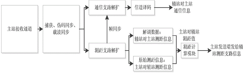
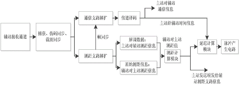
[0025] Step 1: The main station and the auxiliary station are powered on and working, the main station transmits information to the auxiliary station, and the auxiliary station re-up-converts the data and forwards it to the main station after the pseudo code capture and pseudo code tracking, and the main station does the same for the forwarded data Perform pseudocode capture and tracking, so that the tw...


PUM


Abstract

The invention relates to a method for generating distributed synchronous pulses, and belongs to the technical field of electrocommunication and radars. The method is simple, flexible and convenient to adjust. For a 100M system clock, the phase adjustment time is short, and only a few FPGA resources are occupied.

Description

technical field [0001] The invention relates to a method for generating distributed synchronous pulses, belonging to the technical fields of electronic communication and radar. Background technique [0002] Radar plays an irreplaceable role in modern and future electronic warfare, but the original monostatic radar with integrated transceiver faces four threats: electronic jamming, ultra-low altitude penetration, stealth weapons, and anti-radiation missiles. In contrast, the bistatic or multistatic radar system has changed the traditional single-base system in which the transmitting station T and the receiving station R are in the same position, and separates the T station and the R station, which has strong survivability and high The detection function has attracted people's attention, and has been further developed rapidly and widely used. However, one of the important technical issues is the time synchronization of transceiver stations. The radar needs to measure the targ...

Claims


Application Information

Patent Timeline
Patent Type & Authority Applications(China)
IPC IPC(8): H04L7/033
Inventor 安建平杜昌澔韩航程梁丹丹
Owner BEIJING INSTITUTE OF TECHNOLOGYGY
Why Eureka
Try Eureka