Sensor element having a piezoelectric transducer

A sensor element, piezoelectric transducer technology, applied in electrical components, fluid pressure measurement using piezoelectric devices, measurement of properties using piezoelectric devices, etc., can solve the problems of high circuit technology, intractability, and cost. , to achieve the effect of high resolution and small area requirements

Active Publication Date: 2014-02-05
ROBERT BOSCH GMBH
View PDF8 Cites 5 Cited by
  • Summary
  • Abstract
  • Description
  • Claims
  • Application Information

AI Technical Summary

Problems solved by technology

Therefore, a high circuit-technical outlay must be incurred for amplifying or converting the signal of the piezoelectric transducer, which results in the entire arrangement being relatively large and difficult to handle, for example, for installation in a motor vehicle.

Method used


Image

  • Sensor element having a piezoelectric transducer
  • Sensor element having a piezoelectric transducer
  • Sensor element having a piezoelectric transducer

Examples


Embodiment Construction

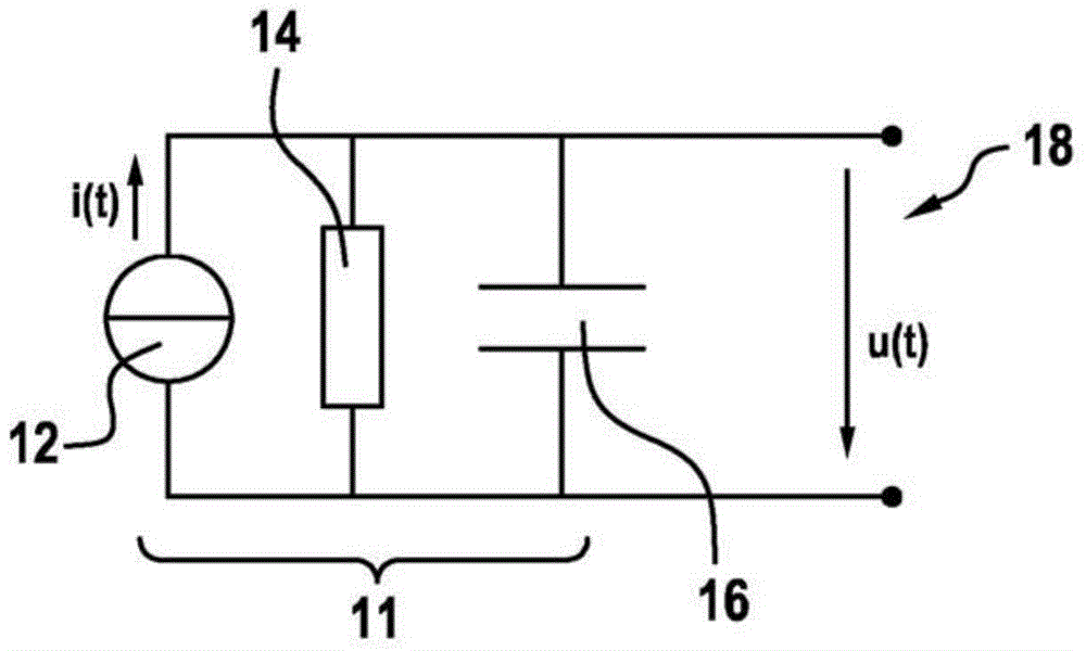
[0033] figure 1 An equivalent circuit diagram of the piezoelectric transducer 11 is shown. The equivalent circuit diagram of the piezoelectric transducer 11 includes a current source 12 simulating the piezoelectric effect. Furthermore, the current intensity i(t) has a distribution related to the piezoelectric sensitivity k and the force F to be converted:

[0034] i(t)=kδF(t) / δt.

[0035] In addition, an internal resistance 14 and a capacitor 16 are connected to the current source 12 in parallel. An output voltage u(t) of the piezoelectric converter 11 is generated at an output 18 .

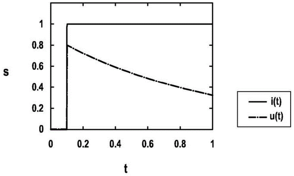
[0036] figure 2 show the basis figure 1 The step response of the piezoelectric converter 11 , that is to say the resulting output voltage u(t) at a stepped input current intensity i(t). A step response or a stepwise change of the input current intensity i(t) is achieved, for example, by exerting a force surge on the converter 11 . figure 2 The behavior of piezoelectric transducer 11 is s...


PUM


Abstract

The invention relates to a sensor element (10) having at least one piezoelectric transducer (11), said piezoelectric transducer (11) being coupled to at least one memristor (20). The invention further relates to a sensor having an array of a plurality of pixels, at least one of the pixels comprising a sensor element (10).

Description

technical field [0001] The invention relates to a sensor element having at least one piezoelectric transducer. Background technique [0002] The piezoelectric effect is well known and well used in the art to measure applied force. In this case, the force leads to an elastic deformation of the beam or membrane and thus to a change in the electrical polarization in the material. This results in charge separation, which in turn can be detected as a voltage. The piezoelectric effect only occurs in certain materials. Among these materials are, for example, quartz, lead zirconate titanate (PZT), aluminum nitride (AIN) and certain ceramics. [0003] However, charge separation in piezoelectric transducers has a longer or shorter duration depending on the material and surrounding circuitry, that is, the applied force changes from a first constant level to a second constant level (step) in a longer or shorter duration. "Forgotten" by the converter after a short time. This means t...

Claims


Application Information

Patent Timeline
Patent Type & Authority Applications(China)
IPC IPC(8): G01L1/16H01L41/113
CPCH01L41/042H01L41/1132G01L9/08G01L1/16H10N30/802H10N30/302
Inventor A·弗兰克A·比曼F·亨里奇
Owner ROBERT BOSCH GMBH
Why Eureka
Try Eureka