Extrusion forming device and method for crank shaft and crank throw for large-size ship

An extrusion forming and marine technology, which is applied to the extrusion forming device of large marine crankshaft crankshaft and the forming field of large marine crankshaft crankshaft, can solve the problems of difficult forming, difficult operation and complicated process, and reduce machining The effect of margin, high degree of continuity and good metal flow

Active Publication Date: 2014-02-12
SHANGHAI ELECTRIC SHMP CASTING & FORGING CO LTD +1
View PDF6 Cites 5 Cited by
  • Summary
  • Abstract
  • Description
  • Claims
  • Application Information

AI Technical Summary

Problems solved by technology

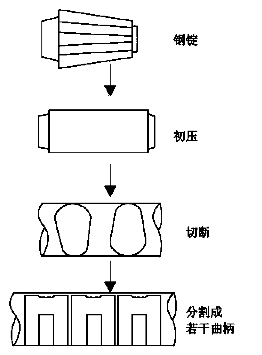
The advantages of this method are: simple shape, easy forming, no need for molds, and less forging times; the allowance of the crank throw forged by this method can be appropriately reduced, and the middle connecting rod position is cut off, and then machined into shape The disadvantage of this method is that the fibrous structure of the forged steel crank throw is cut off in the middle and is discontinuous, which will affect the performance
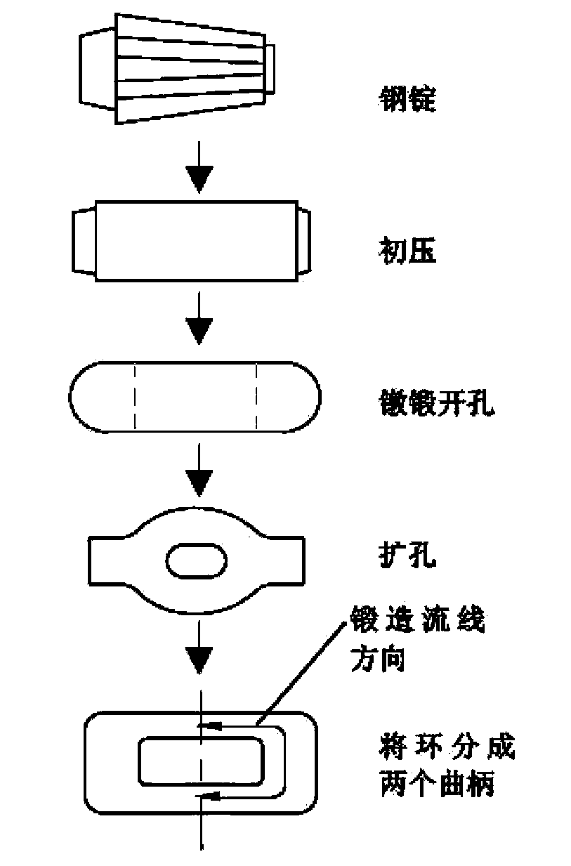
The disadvantages of this method are: difficult forming, complicated process, poor material utilization and formability, and defects such as pores may appear in forgings
The disadvantages of this method are: large equipment tonnage, difficult operation, and difficult demoulding in the later stage
The disadvantages of this method are: low pass rate, high energy consumption and high cost

Method used


Image

  • Extrusion forming device and method for crank shaft and crank throw for large-size ship
  • Extrusion forming device and method for crank shaft and crank throw for large-size ship
  • Extrusion forming device and method for crank shaft and crank throw for large-size ship

Examples


Embodiment Construction

[0052] The forming method of the large-scale marine crankshaft crank throw of the present invention is used to manufacture a marine crankshaft crank throw with an external dimension not less than 700mm×1100mm×2100mm, such as Figure 5 to Figure 7 The bellcrank extrusion forming device shown in the figure includes a lower cavity formed by two chute 7 and two lower side plates 6, an upper cavity formed by two upper chute 4 and two upper side plates 3. Cavity, the lower cavity is located above the upper cavity; the lower cavity is provided with a die 8;

[0053] The inboard of each upper chute 4 is flexibly connected with a slide block 5 by a ramp, and the slide block 5 can slide relative to the upper chute 4 along the ramp; When the top surface of the slider 5 is in contact with the top of the upper cavity (the top of the upper cavity is the top surface of the upper chute 4), the two sliders 5 reach the mold clamping position;

[0054] Since the slider 5 is connected to the upp...


PUM


Abstract

The invention discloses an extrusion forming device for a crank shaft and a crank throw for a large-size ship. The extrusion forming device comprises a lower molded cavity consisting of two lower sliding chutes and two lower side plates and an upper molded cavity consisting of two upper sliding chutes and two upper side plates, wherein the lower molded cavity is positioned above the upper molded cavity; a female die is arranged in the lower molded cavity; the inner side of each upper sliding chute is movably connected with a sliding block through an inclined rail; the sliding blocks can slide along the inclined rails relative to the upper sliding chutes; the contact surfaces of the lower surfaces, which are in contact with the lower sliding chutes, of the sliding blocks are slopes; the two upper side plates are fixedly connected with at least one cylinder; a plunger of each cylinder is fixedly connected with a male die; the male die is fixedly connected with the upper ends of pull rods; the lower ends of the pull rods are movably connected with the upper side plates. According to the extrusion forming device, the machining allowance can be greatly reduced, and the utilization rate of a material can be increased. The extrusion forming device can realize quick demolding and is high in continuous degree, so that the manufacturing period of a product is shortened, the working procedure is short, the efficiency is high, and the operation is simple. The invention also discloses a forming method for the crank shaft and the crank throw for the large-size ship.

Description

technical field [0001] The invention relates to an extrusion forming device, in particular to an extrusion forming device for a crank throw of a large marine crankshaft. The invention also relates to a forming method of a large-scale marine crankshaft. Background technique [0002] The output power of large marine engines generally exceeds 10,000 horsepower. In such an engine, the crank throw for the combined crankshaft is very large, and it is very difficult to manufacture such a large crankshaft throw. [0003] The existing forging methods of large crankshaft throws are as follows: [0004] The first one is the block forging method; the forming process of the block forging method is as follows: figure 1 As shown, the bell crank blank is forged into an angular block. The advantages of this method are: simple shape, easy forming, no need for molds, and less forging times; the allowance of the crank throw forged by this method can be appropriately reduced, and the middle ...

Claims


Application Information

Patent Timeline
Patent Type & Authority Applications(China)
IPC IPC(8): B21C23/02B21C25/02
Inventor 曹峰华任运来齐作玉
Owner SHANGHAI ELECTRIC SHMP CASTING & FORGING CO LTD
Why Eureka
Try Eureka